Nissan Qashqai (2007-2010). Manual — part 119
COOLING FAN
CO-59
< ON-VEHICLE REPAIR >
[K9K]
C
D
E
F
G
H
I
J
K
L
M
A
CO
N
P
O
1.
Remove resistor from fan shroud.
CAUTION:
Handle carefully to avoid dropping and shocks.
2.
Remove cooling fan mounting nut, and then remove the cooling fan.
CAUTION:
Reverse screw is used for the fan attachment screw. When removing or attaching, turn the screw
the opposite way as for a normal screw.
3.
Remove fan motor.
ASSEMBLY
Assembly is the reverse order of disassembly.
• Apply thread locking sealant on fan motor shaft.
Inspection
INFOID:0000000001111180
INSPECTION AFTER DISASSEMBLY
Cooling Fan
Inspect cooling fan for crack or unusual bend.
• If anything is found, replace cooling fan.
CO-60
< ON-VEHICLE REPAIR >
[K9K]
WATER PUMP
WATER PUMP
Exploded View
INFOID:0000000001062345
Removal and Installation
INFOID:0000000001062512
WARNING:
Never remove the radiator cap when the engine is hot. Serious burns could occur from high pressure
coolant escaping from the radiator.
REMOVAL
1.
Remove the following parts.
• Battery ground cable
• Undercover
• RH front wheel
2.
Remove right side splash cover.
3.
Remove drive belt. Refer to
EM-259, "Removal and Installation"
4.
Drain engine coolant. Refer to
CAUTION:
Perform when engine is cold.
5.
Remove timing belt and inner cover. Refer to
EM-287, "Removal and Installation"
6.
Remove the water pump.
• Coolant will leak from the cylinder block, so have a receptacle ready below.
CAUTION:
• Handle the water pump vane so that it does not contact any other parts.
• Water pump cannot be disassembled and should be replaced as a unit.
INSTALLATION
Install in the reverse order of removal.
Inspection
INFOID:0000000001062347
INSPECTION AFTER REMOVAL
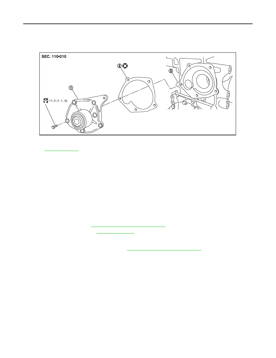
1.
Water pump
2.
Gasket
3.
Cylinder block
Refer to
for symbols not described on the above.
E1BIA0026GB
WATER PUMP
CO-61
< ON-VEHICLE REPAIR >
[K9K]
C
D
E
F
G
H
I
J
K
L
M
A
CO
N
P
O
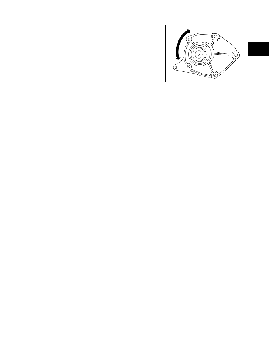
• Visually make sure there is no significant dirt or rusting on the
water pump body and vane.
• Make sure there is no looseness in the vane shaft, and that it turns
smoothly when rotated by hand.
• If there are any unusualness, replace the water pump assembly.
INSPECTION AFTER INSTALLATION
• Check for engine coolant leaks using reservoir tank cap tester. Refer to
MBIB0546E
CO-62
< ON-VEHICLE REPAIR >
[K9K]
WATER OUTLET AND THERMOSTAT ASSEMBLY
WATER OUTLET AND THERMOSTAT ASSEMBLY
Exploded View
INFOID:0000000001062351
Removal and Installation
INFOID:0000000001062517
REMOVAL
1.
Remove engine cover. Refer to
EM-266, "Removal and Installation"
.
2.
Remove air cleaner case and air duct (inlet). Refer to
EM-265, "Removal and Installation"
.
3.
Remove rear engine slinger. Refer to
.
4.
Remove vacuum hose.
5.
Remove vacuum pump. Refer to
EM-276, "Removal and Installation"
6.
Drain engine coolant. Refer to
CAUTION:
Perform when engine is cold.
7.
Remove radiator upper hose. Refer to
8.
Remove heater hose.
9.
Disconnect reservoir tank hose. Refer to
10. Remove water outlet.
INSTALLATION
Install in the reverse order of removal.
Inspection
INFOID:0000000001062513
INSPECTION AFTER REMOVAL
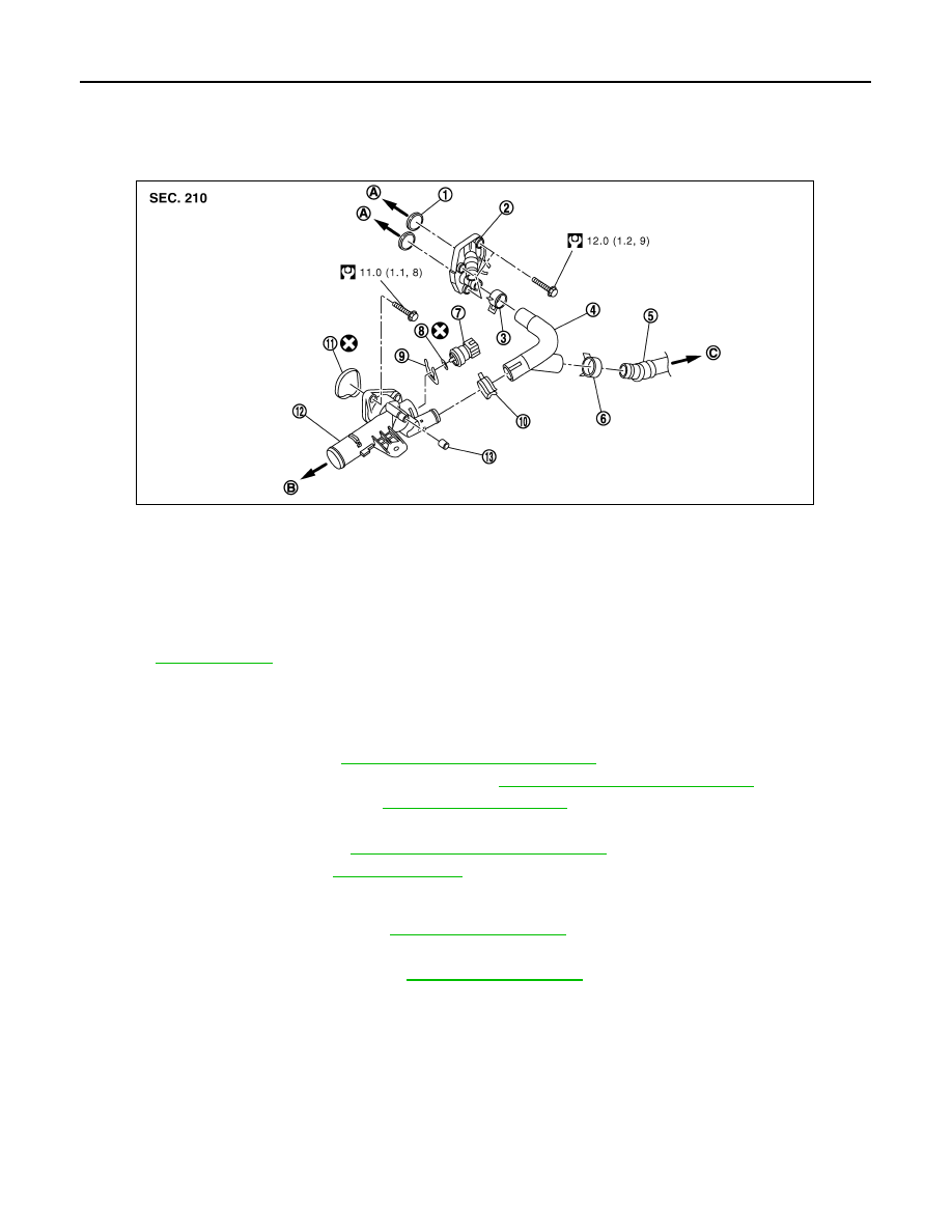
1.
O-ring
2.
EGR cooler cover
3.
Clamp
4.
Water pipe
5.
Heater hose
6.
Clamp
7.
Engine coolant temperature sensor
8.
O-ring
9.
Lock plate
10. Clamp
11.
Gasket
12. Water outlet and thermostat assembly
13. Air relief plug
A.
To EGR volume control valve housing B.
To radiator hose (upper)
C.
To heater core
for symbols not described on the above.
E1BIA0027GB
Нет комментариевНе стесняйтесь поделиться с нами вашим ценным мнением.
Текст