Nissan Qashqai (2007-2010). Manual — part 707
BRC-26
< COMPONENT DIAGNOSIS >
[ABS]
C1109 POWER AND GROUND SYSTEM
C1109 POWER AND GROUND SYSTEM
Description
INFOID:0000000000924978
Power is supply from the battery to ABS actuator and electric unit (control unit).
DTC Logic
INFOID:0000000000924979
DTC DETECTION LOGIC
DTC CONFIRMATION PROCEDURE
1.
CHECK SELF-DIAGNOSIS RESULTS
Check the self-diagnosis results.
Is above displayed on the self-diagnosis display?
YES
>> Proceed to diagnosis procedure. Refer to
.
NO
>> INSPECTION END
Diagnosis Procedure
INFOID:0000000000924980
INSPECTION PROCEDURE
1.
CHECK CONNECTOR
1.
Turn ignition switch OFF.
2.
Disconnect ABS actuator and electric unit (control unit) connector.
3.
Check terminal for deformation, disconnection, looseness, and so on. If any malfunction is found, repair or
replace terminal.
4.
Reconnect connector and then perform the self-diagnosis. Refer to
.
Is any item indicated on the self-diagnosis display?
YES
>> GO TO 2.
NO
>> Poor connection of connector terminal. Repair or replace connector.
2.
CHECK ABS ACTUATOR AND ELECTRIC UNIT (CONTROL UNIT) POWER SUPPLY CIRCUIT
1.
Turn ignition switch OFF.
2.
Disconnect ABS actuator and electric unit (control unit) connector.
3.
Turn ignition switch ON or OFF and check voltage between ABS actuator and electric unit (control unit)
harness connector terminal and ground.
4.
Reconnect ABS actuator and electric unit (control unit) connector.
Is the inspection result normal?
YES
>> GO TO 3.
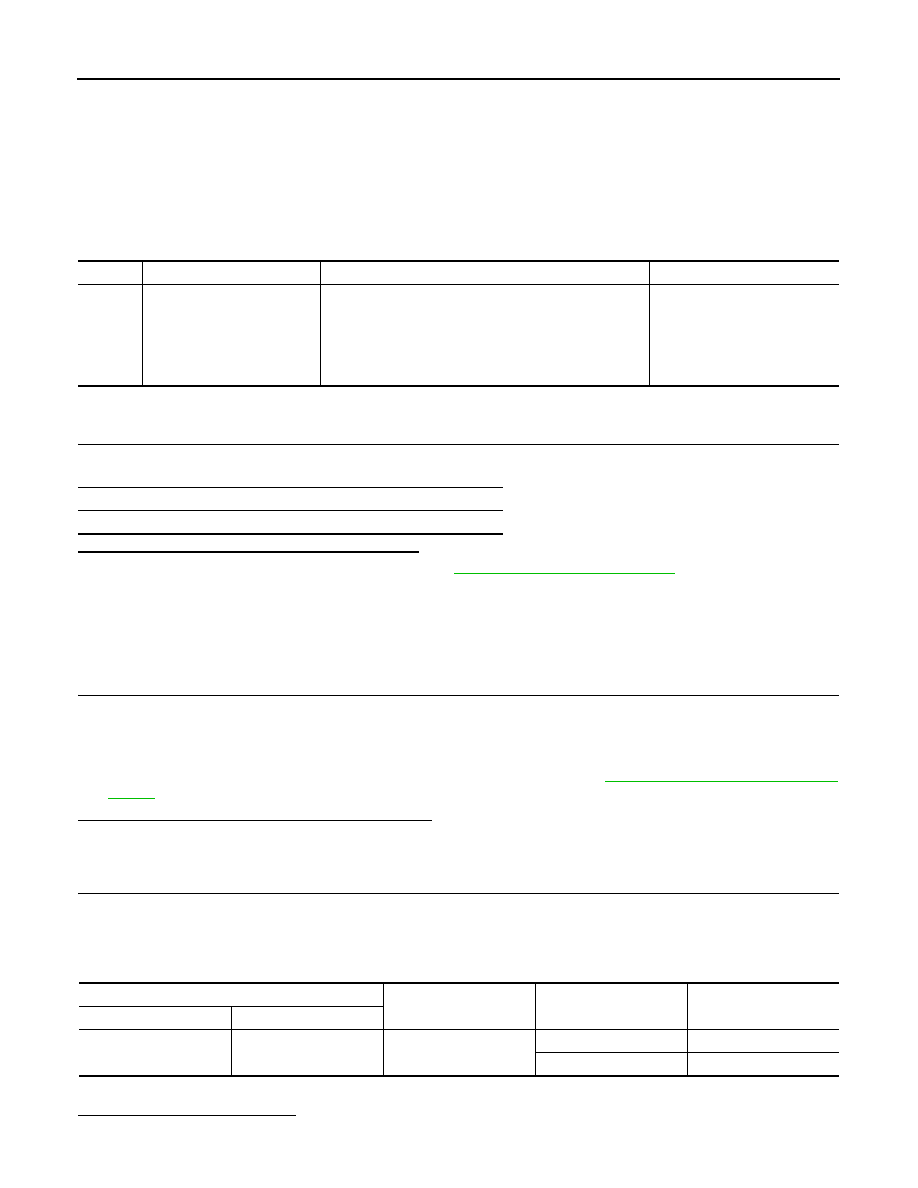
DTC
Display item
Malfunction detected condition
Possible cause
C1109
BATTERY VOLTAGE
[ABNORMAL]
When the ABS actuator and electric unit (control unit)
power supply is lower than normal and vehicle speed is
greater than 6 km/h (4 MPH). Power supply is greater
than normal limits.
• Harness or connector
• ABS actuator and electric unit
(control unit)
• Fuse
• Vehicle electrical power sys-
tem
Self-diagnosis results
BATTERY VOLTAGE [ABNORMAL]
ABS actuator and electric unit (control unit)
—
Condition
Voltage
Connector
Terminal
E34
18
Ground
Ignition switch: ON
Battery voltage
Ignition switch: OFF
Approx. 0 V
C1109 POWER AND GROUND SYSTEM
BRC-27
< COMPONENT DIAGNOSIS >
[ABS]
C
D
E
G
H
I
J
K
L
M
A
B
BRC
N
O
P
NO
>> Repair or replace malfunctioning components.
3.
ABS POWER SUPPLY CHECK (UNDER LOAD CONDITIONS)
1.
Use 12V lamp (normal rating 10 to 20W) connected between E34 terminals 18 and 4. With ignition switch
ON check bulb illuminates correctly.
2.
Check ABS motor supply under loaded condition (connector E34 terminals 1 and 2).
Is the inspection result normal?
YES
>> GO TO 4.
NO
>> Check both power supply and ground circuit.
4.
CHECK ABS ACTUATOR AND ELECTRIC UNIT (CONTROL UNIT) GROUND CIRCUIT
1.
Turn ignition switch OFF.
2.
Disconnect ABS actuator and electric unit (control unit) connector.
3.
Check continuity between ABS actuator and electric unit (control unit) harness connector terminals and
ground.
Is the inspection result normal?
YES
>> Check battery for terminal looseness, low voltage, etc. if any malfunction is found, repair malfunc-
tioning parts.
NO
>> Repair or replace malfunctioning components (check ABS earth bolt for tightness and corrosion).
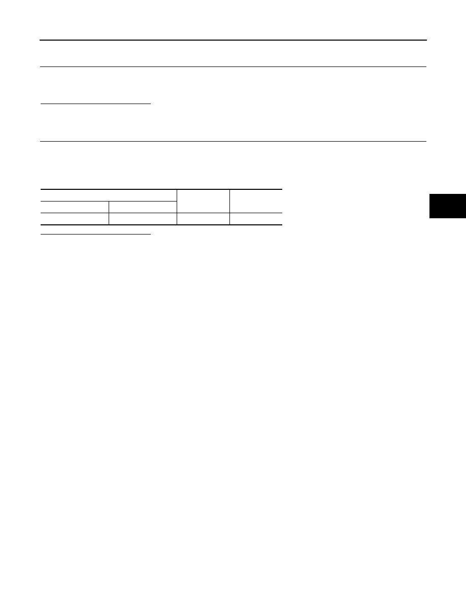
ABS actuator and electric unit (control unit)
—
Continuity
Connector
Terminal
E34
1, 4
Ground
Existed

BRC-28
< COMPONENT DIAGNOSIS >
[ABS]
C1110, C1153 ABS ACTUATOR AND ELECTRIC UNIT (CONTROL UNIT)
C1110, C1153 ABS ACTUATOR AND ELECTRIC UNIT (CONTROL UNIT)
Description
INFOID:0000000001091113
ABS unit is continuously monitoring ECU hardware and software for correct operation.
DTC Logic
INFOID:0000000000924982
DTC DETECTION LOGIC
DTC CONFIRMATION PROCEDURE
1.
CHECK SELF-DIAGNOSIS RESULTS
1.
Check both ABS solenoid valve and motor supply and ground circuits using a suitable electrical load.
2.
Check wheel speed sensor inputs.
3.
Check the self-diagnosis results.
Is above displayed on the self-diagnosis display?
YES
>> Proceed to diagnosis procedure. Refer to
.
NO
>> INSPECTION END
Diagnosis Procedure
INFOID:0000000000924983
INSPECTION PROCEDURE
1.
REPLACE ABS ACTUATOR AND ELECTRIC UNIT (CONTROL UNIT)
CAUTION:
Replace ABS actuator and electric unit (control unit) when self-diagnostic result shows items other
than those applicable.
>> Replace ABS actuator and electric unit (control unit).
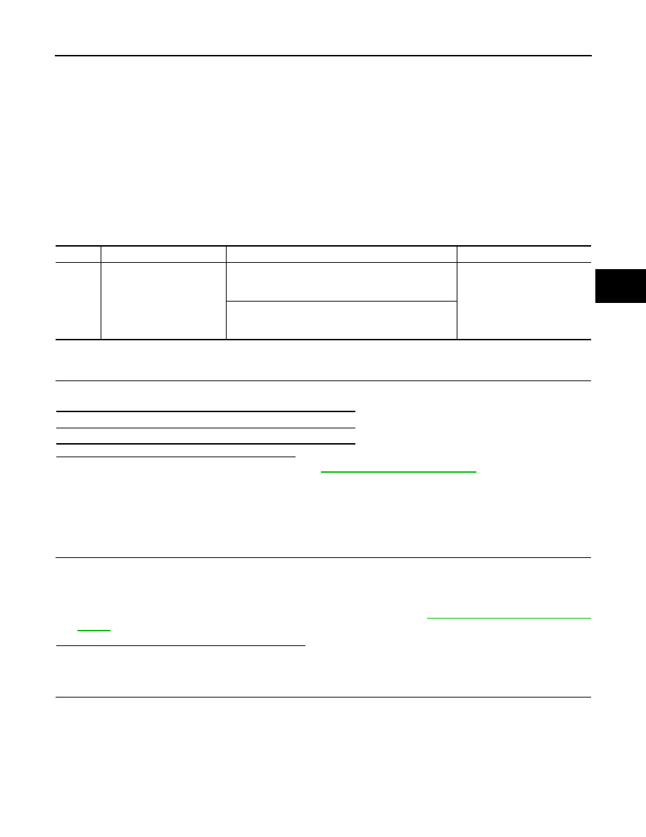
DTC
Display item
Malfunction detected condition
Possible cause
C1110
CONTROLLER FAILURE
Possible internal failure of control unit components.
• Internal failure of control unit
components
• ABS solenoid valve or motor
power supply/ground abnor-
mality
C1153
EMERGENCY BRAKE
Continuous ABS/EBD control for more than 60 seconds.
• ABS control unit software fail-
ure
• Wheel speed sensor input
abnormality
Self-diagnosis results
CONTROLLER FAILURE
EMERGENCY BRAKE
C1111 ABS MOTOR, MOTOR RELAY SYSTEM
BRC-29
< COMPONENT DIAGNOSIS >
[ABS]
C
D
E
G
H
I
J
K
L
M
A
B
BRC
N
O
P
C1111 ABS MOTOR, MOTOR RELAY SYSTEM
Description
INFOID:0000000000924985
PUMP
The pump returns the brake fluid stored in the reservoir to the master cylinder by reducing the pressure.
MOTOR
The motor drives the pump according to the signals transmitted by the ABS actuator and electric unit (control
unit).
DTC Logic
INFOID:0000000000924986
DTC DETECTION LOGIC
DTC CONFIRMATION PROCEDURE
1.
CHECK SELF-DIAGNOSIS RESULTS
Check the self-diagnosis results.
Is above displayed on the self-diagnosis display?
YES
>> Proceed to diagnosis procedure. Refer to
.
NO
>> INSPECTION END
Diagnosis Procedure
INFOID:0000000000924987
INSPECTION PROCEDURE
1.
CHECK CONNECTOR
1.
Turn ignition switch OFF.
2.
Disconnect ABS actuator and electric unit (control unit) connector.
3.
Check terminal for deformation, disconnect, looseness, and so on. If any malfunction is found, repair or
replace terminal.
4.
Reconnect connector and then perform the self-diagnosis. Refer to
.
Is any item indicated on the self-diagnosis display?
YES
>> GO TO 2.
NO
>> Poor connection of connector terminal. Replace or repair connector.
2.
CHECK ABS MOTOR AND MOTOR RELAY POWER SUPPLY CIRCUIT
1.
Turn ignition switch OFF.
2.
Disconnect ABS actuator and electric unit (control unit) connector.
3.
Check voltage between the ABS actuator and electric unit (control unit) harness connector terminal and
ground.
DTC
Display item
Malfunction detected condition
Possible cause
C1111
PUMP MOTOR
During the actuator motor operating with ON, when the
actuator motor turns OFF, or when the control line for ac-
tuator motor relay is open.
• Harness or connector
• ABS actuator and electric unit
(control unit)
During the actuator motor operating with OFF, when the
actuator motor turns ON, or when the control line for relay
is shorted to ground.
Self-diagnosis results
PUMP MOTOR
Нет комментариевНе стесняйтесь поделиться с нами вашим ценным мнением.
Текст