Nissan Qashqai (2007-2010). Manual — part 668
FRONT COIL SPRING AND STRUT
FSU-9
< ON-VEHICLE REPAIR >
C
D
F
G
H
I
J
K
L
M
A
B
FSU
N
O
P
ON-VEHICLE REPAIR
FRONT COIL SPRING AND STRUT
Exploded View
INFOID:0000000000970530
Removal and Installation
INFOID:0000000000970531
REMOVAL
1.
Remove tires from vehicle.
2.
Remove lock plat.
BR-19, "FRONT BRAKE (WITH ABS) : Exploded View"
"FRONT BRAKE (WITH ESP) : Exploded View"
BR-63, "FRONT BRAKE (WITH ABS) :
BR-65, "FRONT BRAKE (WITH ESP) : Exploded View"
(RHD with
ESP).
3.
Remove cap and mounting nut on the upper side of stabilizer connecting rod, and then remove stabilizer
connecting rod from strut assembly.
4.
Separate steering knuckle from strut assembly.
5.
Remove mounting bolts of strut mounting insulator, and then remove strut assembly.
INSTALLATION
Note the following, and install in the reverse order of removal.
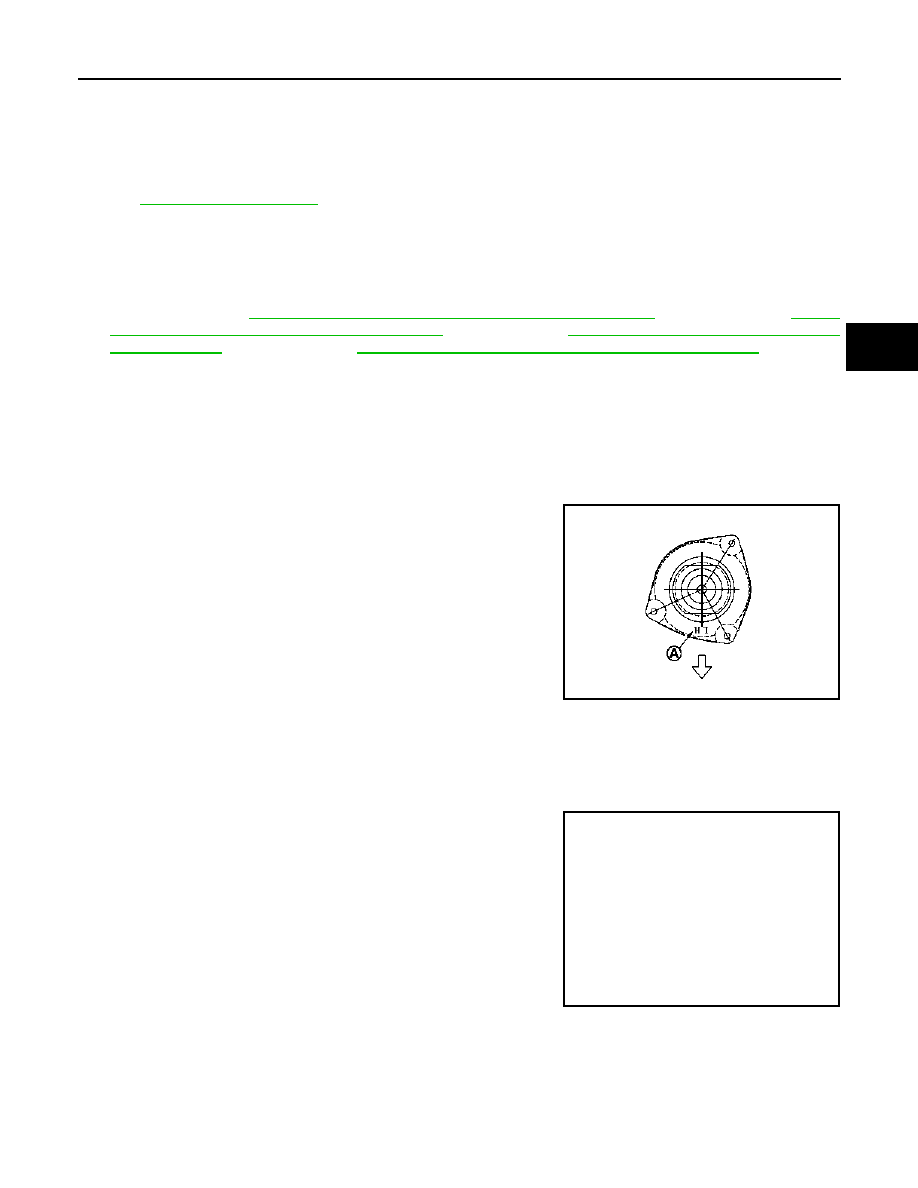
• Make sure the identification mark (A) on strut mounting insulator
as shown in the figure.
• Perform final tightening of bolts and nuts, under unladen conditions
with tires on level ground.
Disassembly and Assembly
INFOID:0000000000970532
DISASSEMBLY
CAUTION:
Never damage strut assembly piston rod when removing components from strut assembly.
1.
Install strut attachment (A) (SST: ST35652000) to strut assem-
bly and secure it in a vise.
CAUTION:
When installing the strut attachment to strut assembly,
wrap a shop cloth around strut to protect from damage.
: Vehicle front
PDIA1228E
JPEIA0006ZZ
FSU-10
< ON-VEHICLE REPAIR >
FRONT COIL SPRING AND STRUT
2.
Using a spring compressor (A) (commercial service tool), com-
press coil spring between strut mounting bearing and lower rub-
ber seat (on strut assembly) until coil spring with a spring
compressor is free.
CAUTION:
Be sure a spring compressor is securely attached to coil
spring. Compress coil spring.
3.
Make sure coil spring with a spring compressor between strut
mounting bearing and lower rubber seat (strut assembly) is free.
And then remove piston rod lock nut while securing the piston
rod tip so that piston rod does not turn.
4.
Remove strut mounting insulator and strut mounting bearing,
and bound bumper from strut.
5.
After remove coil spring with a spring compressor, and then gradually release a spring compressor.
CAUTION:
Loosen while making sure coil spring attachment position does not move.
6.
Remove lower rubber seat from strut.
7.
Remove the strut attachment (SST: ST35652000) from strut.
ASSEMBLY
1.
Install strut attachment (SST: ST35652000) to strut and secure it in a vise.
CAUTION:
When installing the strut attachment to strut assembly, wrap a shop cloth around strut to protect
from damage.
2.
Install lower rubber seat.
3.
Install bound bumper.
4.
Compress coil spring using a spring compressor (commercial service tool), and install it onto strut assem-
bly.
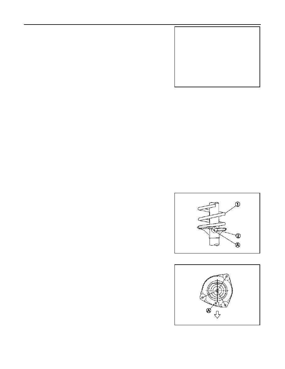
CAUTION:
• Face tube side of coil spring (1) downward. Align the
lower end (A) to lower rubber seat (2).
• Be sure a spring compress is securely attached to coil
spring. Compress coil spring.
5.
Install strut mounting bearing and strut mounting insulator to strut.
• Installation position of strut mounting insulator as shown in the
figure.
6.
Secure piston rod tip so that piston rod does not turn, then
tighten piston rod lock nut with specified torque.
CAUTION:
Never reuse piston rod lock nut.
7.
Gradually release a spring compressor, and remove coil spring.
CAUTION:
Loosen while making sure coil spring attachment position does not move.
8.
Remove the strut attachment from strut assembly.
Inspection
INFOID:0000000000970533
JPEIA0007ZZ
JPEIA0027ZZ
A
: Identification mark
: Vehicle front
PDIA1228E
FRONT COIL SPRING AND STRUT
FSU-11
< ON-VEHICLE REPAIR >
C
D
F
G
H
I
J
K
L
M
A
B
FSU
N
O
P
INSPECTION AFTER INSTALLATION
1.
Adjust neutral position of steering angle sensor. Refer to
BRC-78, "ADJUSTMENT OF STEERING
ANGLE SENSOR NEUTRAL POSITION : Special Repair Requirement"
(with ESP).
2.
Check wheel alignment. Refer to
FSU-7, "Wheel Alignment Inspection"
.
INSPECTION AFTER DISASSEMBLY
Strut
Check the following items, and replace the parts if necessary.
• Strut for deformation, cracks or damage
• Piston rod for damage, uneven wear or distortion
• For oil leakage
Strut Mounting Insulator and Rubber Parts Inspection
Check strut mounting insulator for cracks and rubber parts for wear. Replace it if necessary.
Coil Spring
Check coil spring for cracks, wear or damage. Replace it if necessary.
FSU-12
< ON-VEHICLE REPAIR >
TRANSVERSE LINK
TRANSVERSE LINK
Exploded View
INFOID:0000000000970534
Removal and Installation
INFOID:0000000000970535
REMOVAL
1.
Remove tires from vehicle.
2.
Remove transverse link from steering knuckle.
3.
Remove transverse link from suspension member.
NOTE:
Transverse link cannot be pulled out because the mounting bolt
(
) of transverse link at the rear of the mounting area located
on the front side of vehicle hits against the stabilizer bar. There-
fore, get stabilizer bar out of the way to remove the transverse
link.
INSTALLATION
Note the following, and install in the reverse order of removal.
• Perform final tightening of bolts and nuts at the front suspension member, under unladen conditions with
tires on level ground.
Inspection
INFOID:0000000000970536
INSPECTION AFTER REMOVAL
Visual Inspection
Check the following:
• Transverse link and bushing for deformation, cracks or damage. Replace it if necessary.
• Ball joint boot for cracks or other damage, and also for grease leakage. Replace it if necessary.
Ball Joint Inspection
Manually move ball stud to confirm it moves smoothly with no binding.
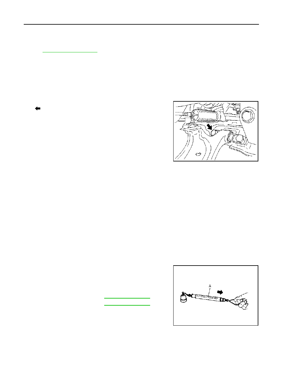
Swing Torque Inspection
NOTE:
Before measurement, move ball stud at least ten times by hand to check for smooth movement.
• Hook a spring balance (A) at cotter pin mounting hole. Confirm
spring balance measurement value is within specifications when
ball stud begins moving.
- If swing torque exceeds standard range, replace transverse link
assembly.
Axial End Play Inspection
• Move tip of ball stud in axial direction to check for looseness.
SEIA0633J
Standard
Swing torque
Spring balance
measurement
JPEIA0005ZZ
Нет комментариевНе стесняйтесь поделиться с нами вашим ценным мнением.
Текст