Nissan Qashqai (2007-2010). Manual — part 497
FL-24
< ON-VEHICLE MAINTENANCE >
[K9K]
FUEL FILTER
1.
Prime the circuit using the priming bulb (1).
2.
Perform engine cranking with repeating several times until
engine starting.
3.
If the engine does not start, use a flat bladed screwdriver to lift
up the button on the fuel return pipe and perform engine crank-
ing.
4.
When the bleeding is completed, push the button, and check
absence of leakage.
: Bleeding position
: Normal position
Inspection
INFOID:0000000001062561
INSPECTION AFTER REPLACEMENT
Check fuel filter for fuel leakage, damage and other abnormal signs.
E1BIA0031ZZ
MBIB9038E
FUEL LEVEL SENSOR UNIT
FL-25
< ON-VEHICLE REPAIR >
[K9K]
C
D
E
F
G
H
I
J
K
L
M
A
FL
N
P
O
ON-VEHICLE REPAIR
FUEL LEVEL SENSOR UNIT
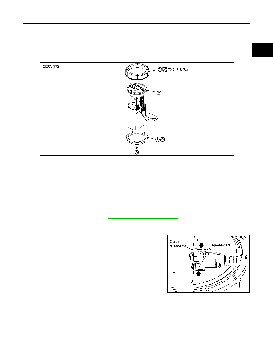
Exploded View
INFOID:0000000001062537
Removal and Installation
INFOID:0000000001062569
REMOVAL
1.
Disconnect battery ground cable.
2.
Open fuel filler lid and filler cap to release the pressure inside the fuel tank.
3.
Remove rear seat cushion. Refer to
SE-31, "Removal and Installation"
.
4.
Remove inspection hole cover under the rear seat.
5.
Disconnect electrical connector.
6.
Disconnect the quick connectors.
• Hold the connector while pushing in tabs, and pull out the
tube.
1.
Rock ring
2.
Fuel level sensor unit
3.
Seal packing
A.
To fuel tank
Refer to
for symbols not described on the above.
E1BIA0015GB
MBIB1052E
FL-26
< ON-VEHICLE REPAIR >
[K9K]
FUEL LEVEL SENSOR UNIT
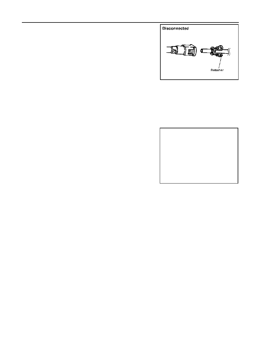
CAUTION:
• The tube can be removed when the tabs are completely depressed. Do not twist it more than
necessary.
• Do not use any tools to remove the quick connector.
• Keep the resin tube away from heat. Be especially careful when welding near the tube.
• Prevent acid liquid such as battery electrolyte etc. from getting on the resin tube.
• Do not bend or twist the tube during installation and removal.
• Only when the tube is replaced, remove the remaining retainer.
• When the tube is replaced, also replace the retainer with a new one.
7.
Using lock ring wrench [SST: KV993G0010], remove lock ring
(2).
CAUTION:
Rotate SST while pressing fuel level sensor unit as spring
reaction force is applied from fuel tank inside to up ward.
8.
Remove fuel level sensor unit(1).
CAUTION:
• Be careful not to bend the float arm when removing.
• Handle them carefully without subjecting them to impacts
such as dropping.
INSTALLATION
Install in the reverse order of removal.
JFE628A
E1BIA0033ZZ
FUEL TANK
FL-27
< ON-VEHICLE REPAIR >
[K9K]
C
D
E
F
G
H
I
J
K
L
M
A
FL
N
P
O
FUEL TANK
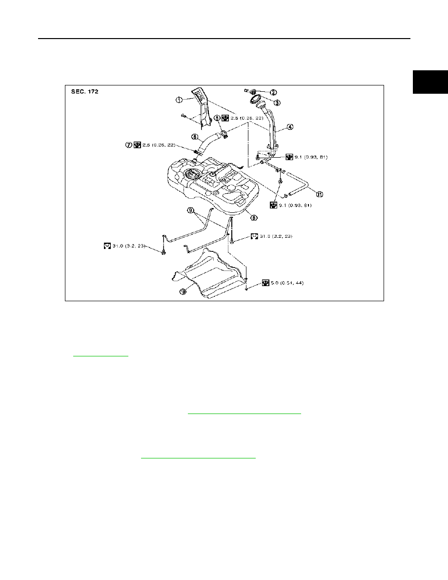
Exploded View
INFOID:0000000001062540
Removal and Installation
INFOID:0000000001062571
REMOVAL
1.
Remove RH rear wheel.
2.
Remove fuel level sensor unit. Refer to
FL-25, "Removal and Installation"
.
CAUTION:
If fuel tank bottom face is not level, and remaining fuel level is high, tank position becomes unsta-
ble, causing a danger. Drain fuel further than that in step 1 of the referenced procedure until tank
can be held by hand even if the balance is lost.
3.
Remove muffler. Refer to
EX-15, "Removal and Installation"
4.
Remove vehicle side insulator on upper center muffler and main muffler.
5.
Move parking brake cable from the lower face of fuel tank. Then remove clips for parking brake cable.
1.
Fuel filler tube protector
2.
Fuel filler cap
3.
Fuel filler cap protector
4.
Fuel filler tube
5.
Clamp
6.
Fuel filler hose
7.
Clamp
8.
Fuel tank
9.
Fuel tank mounting band
10. Fuel tank protector
11.
Vent hose
Refer to
for symbols not described on the above.
E1BIA0014GB
Нет комментариевНе стесняйтесь поделиться с нами вашим ценным мнением.
Текст