Nissan Qashqai (2007-2010). Manual — part 495
FL-16
< ON-VEHICLE REPAIR >
[HR16DE, MR20DE]
FUEL TANK
4.
Remove protector from fuel tank.
5.
Remove vent hose (1) at rear side of fuel tank.
6.
Disconnect EVAP tube (2) at rear side of fuel tank.
• Manual for quick connector (A) of EVAP tube. Refer to
7.
Remove fuel filler hose (3) at fuel filler tube side.
8.
Support center of fuel tank (1) with transmission jack (A).
CAUTION:
Securely support the fuel tank with a piece of wood (B).
9.
Remove fuel tank band (RH and LH).
10. Lower transmission jack carefully to remove fuel tank while holding it by hand.
CAUTION:
Fuel tank may be in an unstable condition because of the shape of fuel tank bottom. Never rely on
jack too much. Be sure to hold tank securely.
INSTALLATION
Note the following, and install in the reverse order of removal.
Fuel Filler Hose
• Insert fuel filler hose to the length below.
• Be sure hose clamp is not placed on swelled area of fuel filler tube.
• Tighten fuel filler hose clamp so that the remaining length of screw thread becomes to the following.
EVAP Hose
1.
Check connections for damage or foreign material.
2.
Align the matching side connection part with the center of shaft,
and insert connector straight until it clicks.
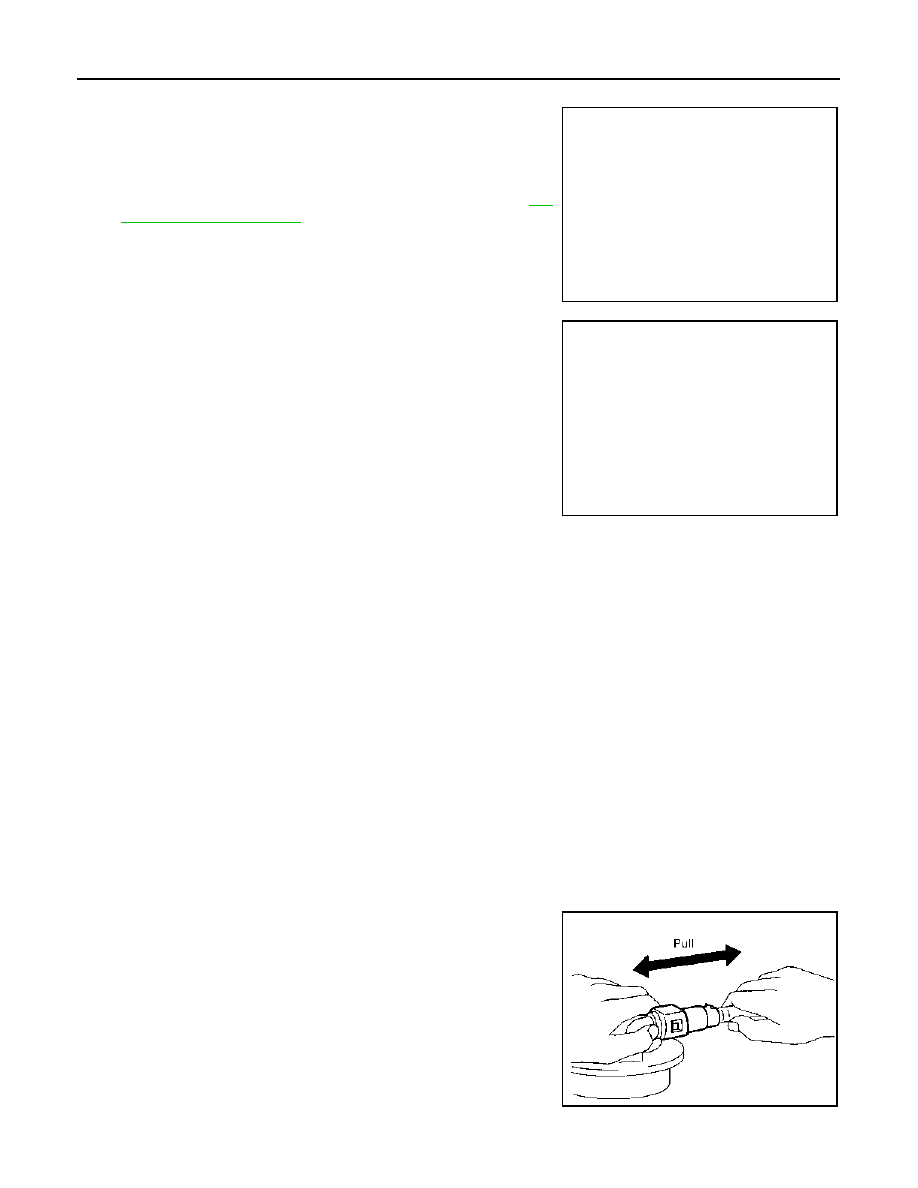
3.
After connecting, pull out quick connector and centralized under-
floor piping by hand. Make sure connections are secure.
2WD : Inspection
INFOID:0000000000905656
: Vehicle front
JPBIA0456ZZ
PBIC3792E
: 35 mm (1.38 in)
Fuel filler tube side
: 7 - 11 mm (0.28 - 0.43 in)
Fuel tank side
: 5 - 9 mm (0.20 - 0.35 in)
PBIC1653E
FUEL TANK
FL-17
< ON-VEHICLE REPAIR >
[HR16DE, MR20DE]
C
D
E
F
G
H
I
J
K
L
M
A
FL
N
P
O
INSPECTION AFTER INSTALLATION
Use the following procedure to check for fuel leaks.
1.
Turn ignition switch “ON” (with engine stopped), and check connections for leakage by applying fuel pres-
sure to fuel piping.
2.
Start engine and rev it up and make sure there are no fuel leaks at the fuel system tube and hose connec-
tions.
4WD
4WD : Exploded View
INFOID:0000000001078683
4WD
4WD : Removal and Installation
INFOID:0000000001078684
REMOVAL
WARNING:
Be sure to read “General Precautions” when working on the fuel system. Refer to
.
1.
Perform the steps 2 to 7 of “REMOVAL” in “ FUEL LEVEL SENSOR UNIT, FUEL FILTER AND FUEL
PUMP ASSEMBLY”. Refer to
FL-11, "4WD : Removal and Installation"
2.
Drain fuel from fuel tank if necessary. Refer to
FL-11, "4WD : Removal and Installation"
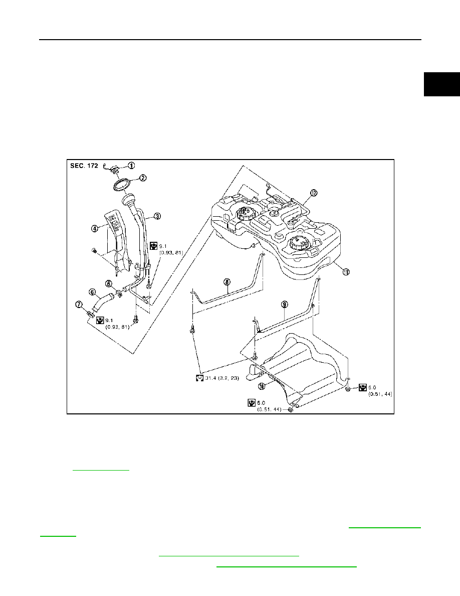
1.
Fuel filler cap
2.
Grommet
3.
Fuel filler tube
4.
Cover
5.
Clamp
6.
Fuel filler hose
7.
Clamp
8.
Fuel tank band (RH)
9.
Fuel tank band (LH)
10. Protector
11.
Fuel tank
12. Vent hose
for to symbols in the figure.
JPBIA0302GB
FL-18
< ON-VEHICLE REPAIR >
[HR16DE, MR20DE]
FUEL TANK
CAUTION:
• Because fuel tank forwardly inclines and becomes unstable when installing/removing, fuel
should be drained if found the remaining quantity.
• Situate vehicle on a flat and solid surface.
3.
Remove propeller shaft. Refer to
.
4.
Remove main muffler. Refer to
.
5.
Remove protector from fuel tank.
6.
Remove vent hose (1) at rear side of fuel tank.
7.
Disconnect EVAP tube (2) at rear side of fuel tank.
• Manual for quick connector (A) of EVAP tube. Refer to
8.
Remove fuel filler hose (3) at fuel filler tube side.
9.
Support center of fuel tank (1) with transmission jack (A).
CAUTION:
Securely support the fuel tank with a piece of wood (B).
10. Remove fuel tank band (RH and LH).
11. Lower transmission jack carefully to remove fuel tank while holding it by hand.
CAUTION:
Fuel tank may be in an unstable condition because of the shape of fuel tank bottom. Never rely on
jack too much. Be sure to hold tank securely.
INSTALLATION
Note the following, and install in the reverse order of removal.
Fuel Filler Hose
• Insert fuel filler hose to the length below.
• Be sure hose clamp is not placed on swelled area of fuel filler tube.
• Tighten fuel filler hose clamp so that the remaining length of screw thread becomes to the following.
EVAP Hose
: Vehicle front
JPBIA0456ZZ
PBIC3792E
: 35 mm (1.38 in)
Fuel filler tube side
: 7 - 11 mm (0.28 - 0.43 in)
Fuel tank side
: 5 - 9 mm (0.20 - 0.35 in)
FUEL TANK
FL-19
< ON-VEHICLE REPAIR >
[HR16DE, MR20DE]
C
D
E
F
G
H
I
J
K
L
M
A
FL
N
P
O
1.
Check connections for damage or foreign material.
2.
Align the matching side connection part with the center of shaft,
and insert connector straight until it clicks.
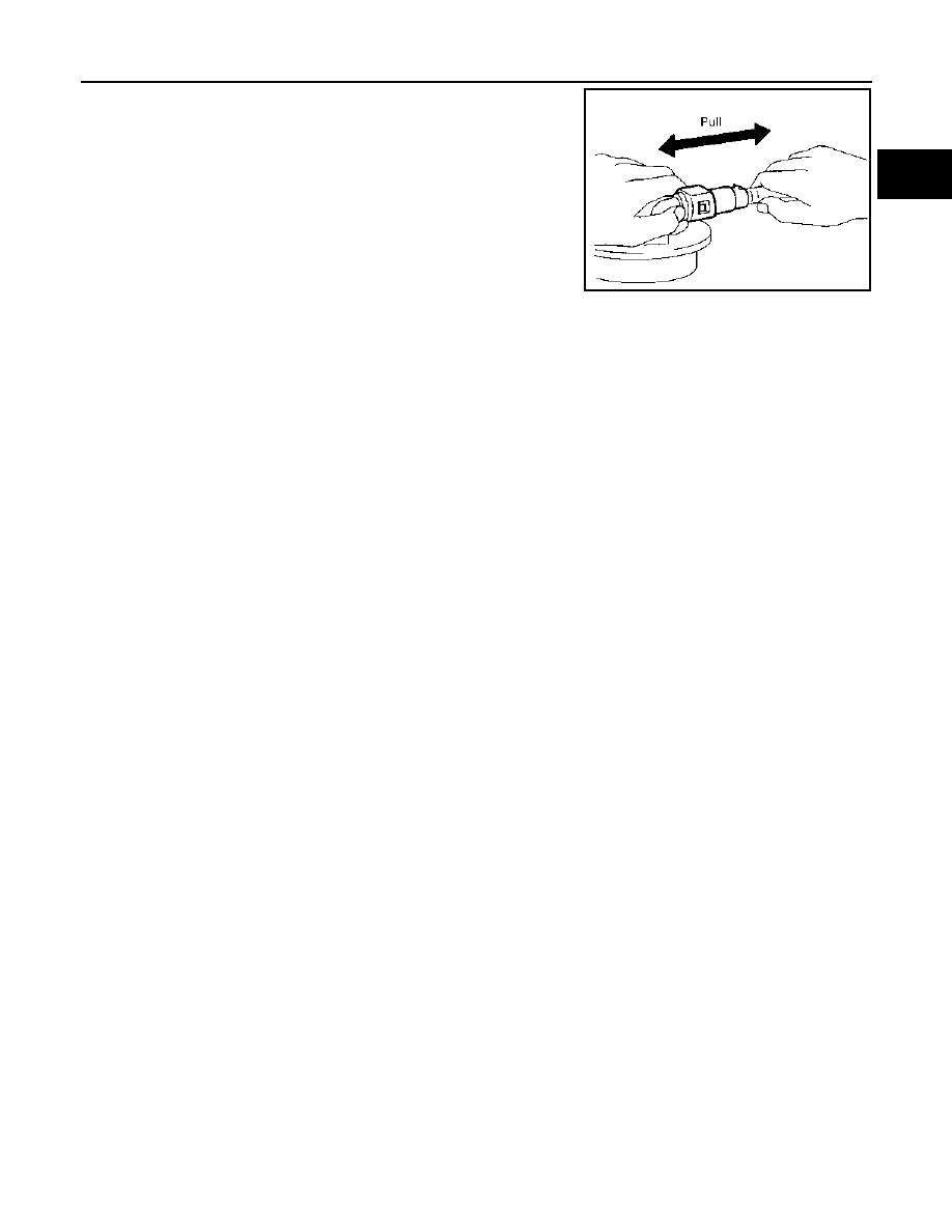
3.
After connecting, pull out quick connector and centralized under-
floor piping by hand. Make sure connections are secure.
4WD : Inspection
INFOID:0000000001078685
INSPECTION AFTER INSTALLATION
Use the following procedure to check for fuel leaks.
1.
Turn ignition switch “ON” (with engine stopped), and check connections for leakage by applying fuel pres-
sure to fuel piping.
2.
Start engine and rev it up and make sure there are no fuel leaks at the fuel system tube and hose connec-
tions.
PBIC1653E
Нет комментариевНе стесняйтесь поделиться с нами вашим ценным мнением.
Текст