Nissan Qashqai (2007-2010). Manual — part 655
FAX-42
< SERVICE DATA AND SPECIFICATIONS (SDS)
[2WD]
SERVICE DATA AND SPECIFICATIONS (SDS)
K9K
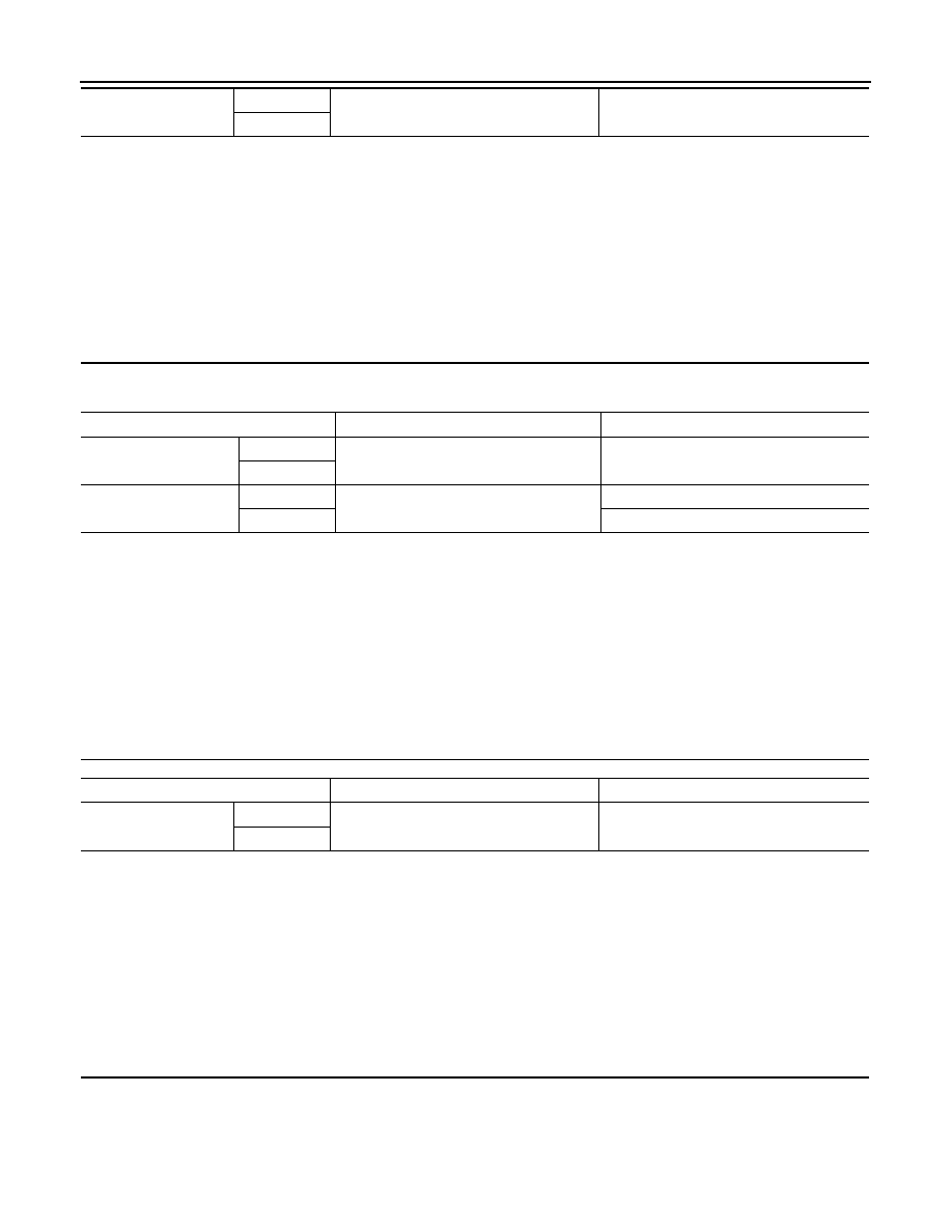
Dimension
Left side
282 – 286 mm (11.10 – 11.26 in)
70 mm (2.76 in)
Right side
FAC0156D
Joint
Wheel side
Transaxle assembly side
Grease quantity
Left side
115 – 135 g (4.06 – 4.76 oz)
215 – 235 g (7.58 – 8.29 oz)
Right side
Boots installed length (L)
Left side
133.5 mm (5.26 in)
186.3 mm (7.33 in)
Right side
173.1 mm (6.81 in)
Dynamic damper
A
B
Dimension
Left side
281 – 285 mm (11.06 – 11.22 in)
70 mm (2.76 in)
Right side
JPDIF0031ZZ
FAC0156D
NOISE, VIBRATION AND HARSHNESS (NVH) TROUBLESHOOTING
FAX-43
< SYMPTOM DIAGNOSIS >
[4WD]
C
E
F
G
H
I
J
K
L
M
A
B
FAX
N
O
P
SYMPTOM DIAGNOSIS
NOISE, VIBRATION AND HARSHNESS (NVH) TROUBLESHOOTING
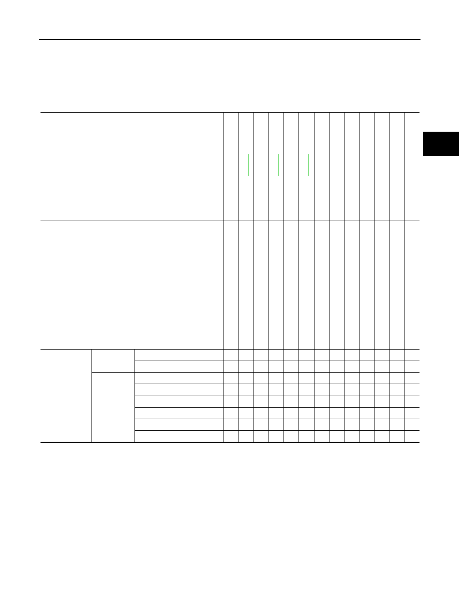
NVH Troubleshooting Chart
INFOID:0000000001080607
Use chart below to find the cause of the symptom. If necessary, repair or replace these parts.
×
: Applicable
Reference page
—
—
—
NV
H in
F
A
X
an
d
FSU s
e
c
tio
ns
Refe
r to
Fro
n
t axle
in
th
is ch
art
NVH in WT
section
NVH in WT
section
Ref
e
r t
o
DRIVE
SHAFT
in this
chart
NVH in BR
section
NVH in S
T
section
Possible cause and SUSPECTED PARTS
Ex
ce
ss
iv
e joi
n
t an
gl
e
Jo
in
t sl
id
in
g
re
si
st
a
n
c
e
Im
ba
la
nc
e
Im
p
rop
er i
n
s
ta
lla
ti
o
n
, lo
os
en
es
s
Part
s interf
erence
Whe
e
l be
ari
n
g
da
ma
ge
FRONT A
X
LE
AND FRONT SUSP
ENSION
FRONT A
X
LE
TI
RE
S
ROAD WHEE
LS
DRIVE SHAFT
BRAKE
S
STE
E
RING
Symptom
DRIVE
SHAFT
Noise
×
×
×
×
×
×
×
×
×
Shake
×
×
×
×
×
×
×
×
×
FRONT
AXLE
Noise
×
×
×
×
×
×
×
×
×
Shake
×
×
×
×
×
×
×
×
×
Vibration
×
×
×
×
×
×
×
Shimmy
×
×
×
×
×
×
×
Judder
×
×
×
×
×
×
Poor quality ride or handling
×
×
×
×
×
FAX-44
< PRECAUTION >
[4WD]
PRECAUTIONS
PRECAUTION
PRECAUTIONS
Precaution for Supplemental Restraint System (SRS) "AIR BAG" and "SEAT BELT
PRE-TENSIONER"
INFOID:0000000001080608
The Supplemental Restraint System such as “AIR BAG” and “SEAT BELT PRE-TENSIONER”, used along
with a front seat belt, helps to reduce the risk or severity of injury to the driver and front passenger for certain
types of collision. This system includes seat belt switch inputs and dual stage front air bag modules. The SRS
system uses the seat belt switches to determine the front air bag deployment, and may only deploy one front
air bag, depending on the severity of a collision and whether the front occupants are belted or unbelted.
Information necessary to service the system safely is included in the SRC and SB section of this Service Man-
ual.
WARNING:
• To avoid rendering the SRS inoperative, which could increase the risk of personal injury or death in
the event of a collision which would result in air bag inflation, all maintenance must be performed by
an authorized NISSAN/INFINITI dealer.
• Improper maintenance, including incorrect removal and installation of the SRS, can lead to personal
injury caused by unintentional activation of the system. For removal of Spiral Cable and Air Bag
Module, see the SRC section.
• Do not use electrical test equipment on any circuit related to the SRS unless instructed to in this
Service Manual. SRS wiring harnesses can be identified by yellow and/or orange harnesses or har-
ness connectors.
Precaution Necessary for Steering Wheel Rotation After Battery Disconnect
INFOID:0000000001099698
NOTE:
• This Procedure is applied only to models with Intelligent Key system and NATS (NISSAN ANTI-THEFT SYS-
TEM).
• Remove and install all control units after disconnecting both battery cables with the ignition knob in the
″
LOCK
″
position.
• Always use CONSULT-III to perform self-diagnosis as a part of each function inspection after finishing work.
If DTC is detected, perform trouble diagnosis according to self-diagnostic results.
For models equipped with the Intelligent Key system and NATS, an electrically controlled steering lock mech-
anism is adopted on the key cylinder.
For this reason, if the battery is disconnected or if the battery is discharged, the steering wheel will lock and
steering wheel rotation will become impossible.
If steering wheel rotation is required when battery power is interrupted, follow the procedure below before
starting the repair operation.
OPERATION PROCEDURE
1.
Connect both battery cables.
NOTE:
Supply power using jumper cables if battery is discharged.
2.
Use the Intelligent Key or mechanical key to turn the ignition switch to the
″
ACC
″
position. At this time, the
steering lock will be released.
3.
Disconnect both battery cables. The steering lock will remain released and the steering wheel can be
rotated.
4.
Perform the necessary repair operation.
5.
When the repair work is completed, return the ignition switch to the
″
LOCK
″
position before connecting
the battery cables. (At this time, the steering lock mechanism will engage.)
6.
Perform a self-diagnosis check of all control units using CONSULT-III.
Precautions for Drive Shaft
INFOID:0000000001117164
CAUTION:
Note the following precautions when disassembling and assembling drive shaft.
• Joint sub-assembly does not disassemble because it is non-overhaul parts.
PRECAUTIONS
FAX-45
< PRECAUTION >
[4WD]
C
E
F
G
H
I
J
K
L
M
A
B
FAX
N
O
P
• Perform work in a dust-free location.
• Before disassembling and assembling, clean the parts.
• Prevent the entry of foreign objects during disassembly of the service location.
• Disassembled parts must be carefully reassembled in the correct order. If work is interrupted, a
clean cover must be placed over parts.
• Paper shop cloths must be used. Fabric shop cloths must not be used because of the danger of lint
adhering to parts.
• Disassembled parts (except for rubber parts) should be cleaned with kerosene which shall be
removed by blowing with air or wiping with paper shop cloths.
Нет комментариевНе стесняйтесь поделиться с нами вашим ценным мнением.
Текст