Nissan Qashqai (2007-2010). Manual — part 634
REAR PROPELLER SHAFT
DLN-109
< ON-VEHICLE MAINTENANCE >
[REAR PROPELLER SHAFT: 3F SPL18-DOJ75]
C
E
F
G
H
I
J
K
L
M
A
B
DLN
N
O
P
ON-VEHICLE MAINTENANCE
REAR PROPELLER SHAFT
Inspection
INFOID:0000000000972152
NOISE
• Check the propeller shaft tube surface for dents or cracks. If damaged, replace propeller shaft assembly.
• If center bearing is noisy or damaged, replace propeller shaft assembly.
VIBRATION
If vibration is present at high speed, inspect propeller shaft runout first.
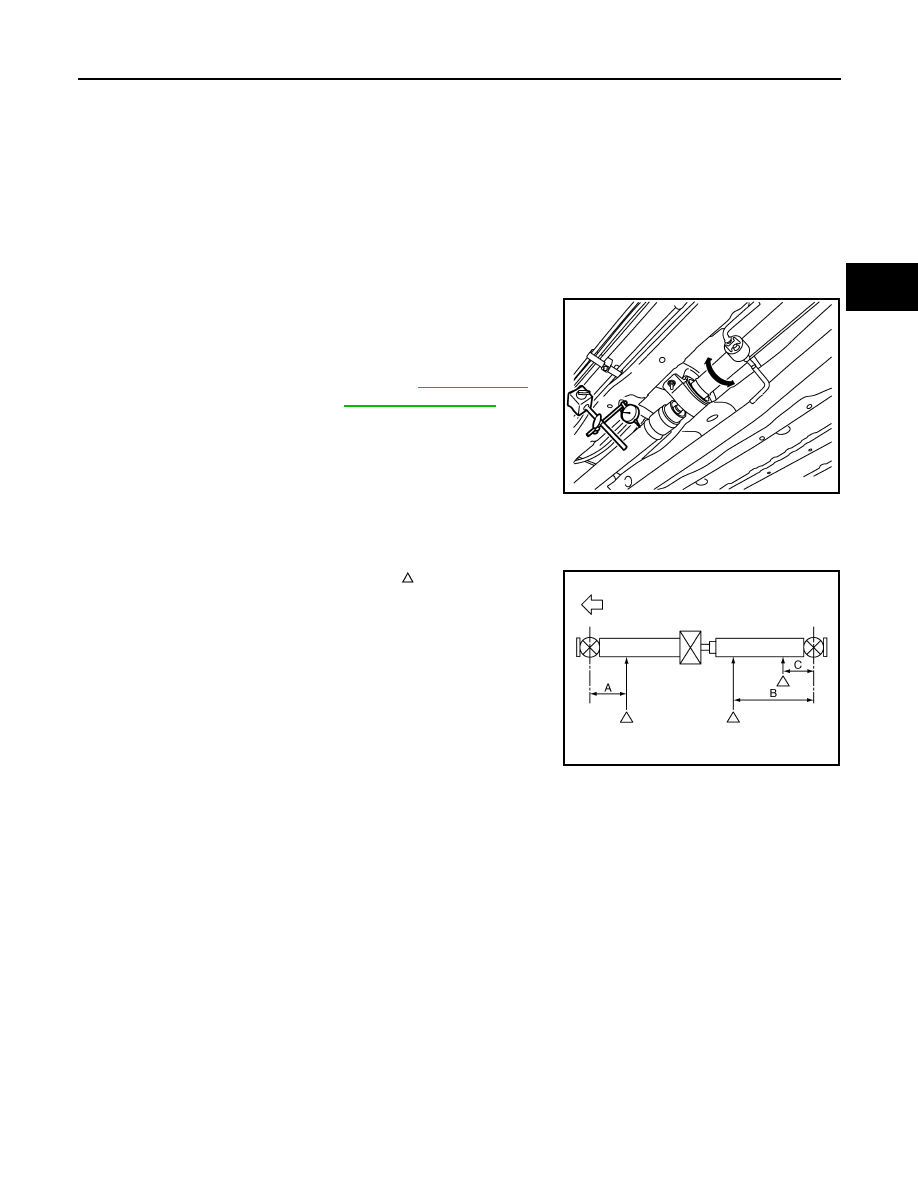
1.
Measure propeller shaft runout at runout measuring points by
rotating final drive companion flange with hands.
2.
If runout still exceeds specifications, separate propeller shaft at
final drive companion flange or transfer companion flange; then
rotate companion flange 90, 180, 270 degrees and install pro-
peller shaft.
3.
Check runout again. If runout still exceeds specifications,
replace propeller shaft assembly.
4.
Check the vibration by driving vehicle.
RUNOUT MEASURING POINT
Propeller shaft runout measuring point (Point “ ”).
Limit
Propeller shaft runout
: Refer to
.
JSDIA0190ZZ
: Vehicle front
Dimension
A: 200 mm (7.87 in)
B: 639 mm (25.16 in)
C: 159 mm (6.26 in)
JSDIA0235ZZ
DLN-110
< ON-VEHICLE REPAIR >
[REAR PROPELLER SHAFT: 3F SPL18-DOJ75]
REAR PROPELLER SHAFT
ON-VEHICLE REPAIR
REAR PROPELLER SHAFT
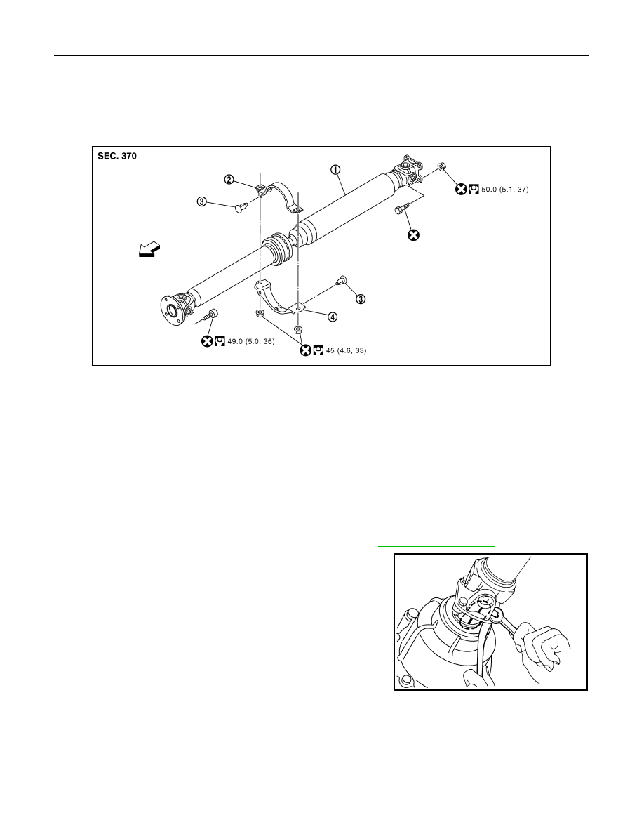
Exploded View
INFOID:0000000000972153
Removal and Installation
INFOID:0000000000972154
REMOVAL
1.
Shift the transaxle to the neutral position, and then release the parking brake.
2.
Remove the main muffler and the exhaust front tube. Refer to
3.
Put matching marks onto propeller shaft flange yoke and final
drive and transfer companion flanges.
CAUTION:
For matching marks, use paint. Never damage propeller
shaft flange yoke and transfer companion flange.
1.
Propeller shaft assembly
2.
Center bearing mounting bracket
(upper)
3.
Clip
4.
Center bearing mounting bracket
(lower)
: Vehicle front
Refer to
for symbols in the figure.
JSDIA0192GB
JSDIA0194ZZ
REAR PROPELLER SHAFT
DLN-111
< ON-VEHICLE REPAIR >
[REAR PROPELLER SHAFT: 3F SPL18-DOJ75]
C
E
F
G
H
I
J
K
L
M
A
B
DLN
N
O
P
4.
Loosen mounting nuts of center bearing mounting brackets.
CAUTION:
Tighten mounting nuts temporarily.
5.
Remove propeller shaft assembly fixing bolts and nuts.
6.
Remove center bearing mounting bracket fixing nuts.
7.
Remove propeller shaft assembly.
CAUTION:
If constant velocity joint was bent during propeller shaft
assembly removal, installation, or transportation, its boot
may be damaged. Wrap boot interference area to metal part with shop cloth or rubber to protect
boot from breakage.
8.
Remove clips and center bearing mounting bracket (upper/lower).
INSTALLATION
Note the following, and install in the reverse order of removal.
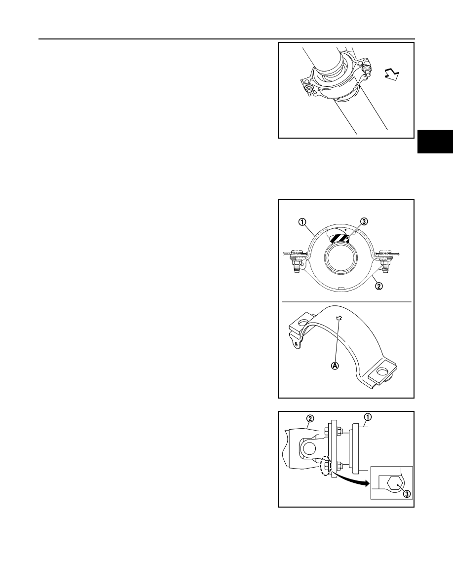
• Install center bearing mounting bracket (upper) (1) with its arrow
mark (A) facing forward.
• Adjust position of center bearing mounting bracket (1), (2) sliding
back and forth to prevent play in thrust direction of center bearing
insulator (3). Install center bearing mounting bracket (upper/lower)
to vehicle.
• Align matching marks to install propeller shaft assembly to final
drive and transfer companion flanges.
• After assembly, perform a driving test to check propeller shaft
vibration. If vibration occurred, separate propeller shaft from final
drive. Reinstall companion flange after rotating it by 90, 180, 270
degrees. Then perform driving test and check propeller shaft vibra-
tion again at each point.
• After tightening the bolts and nuts to the specified torque, make
sure that the bolts (3) on the flange side is tightened as shown in
the figure.
• If propeller shaft assembly or final drive assembly has been replaced, connect them as follows:
: Vehicle front
JSDIA0195ZZ
JSDIA0127ZZ
1
: Final drive assembly
2
: Propeller shaft assembly
JSDIA0196ZZ
DLN-112
< ON-VEHICLE REPAIR >
[REAR PROPELLER SHAFT: 3F SPL18-DOJ75]
REAR PROPELLER SHAFT
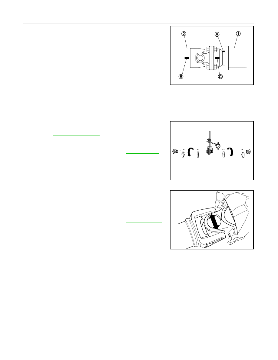
- Face the companion flange mark (A) of the final drive (1) upward.
With the mark (A) faced upward, couple the propeller shaft and the
final drive so that the matching mark (B) of propeller shaft (2) can
be positioned as closest as possible with the matching mark (C) of
the final drive companion flange.
- Tighten mounting bolts and nuts of propeller shaft and final drive to
the specified torque.
Inspection
INFOID:0000000000972155
APPEARANCE
Check propeller shaft for bend and damage. If damage is detected, replace propeller shaft assembly.
PROPELLER SHAFT RUNOUT
Check propeller shaft runout at measuring points. If runout exceeds
specifications, replace propeller shaft assembly. For measuring
point, refer to
.
JOURNAL AXIAL PLAY
As shown in the figure, while fixing yoke on one side, check axial
play of joint. If outside the standard, replace propeller shaft assem-
bly.
CAUTION:
Never disassemble joints.
CENTER BEARING
Check center bearing for noise and damage. If noise or damage is detected, replace propeller shaft assembly.
CAUTION:
Never disassemble center bearing.
PDIA0892J
Limit
Propeller shaft runout
: Refer to
.
JSDIA0193ZZ
Standard
Journal axial play
: Refer to
PDA0005D
Нет комментариевНе стесняйтесь поделиться с нами вашим ценным мнением.
Текст