Nissan Qashqai (2007-2010). Manual — part 971
INSTRUMENT PANEL ASSEMBLY
IP-17
< ON-VEHICLE REPAIR >
C
D
E
F
G
H
I
K
L
M
A
B
IP
N
O
P
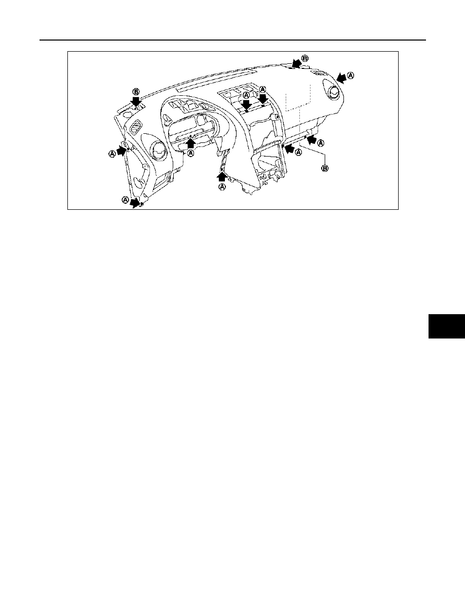
• Remove screws (A) and bolts (B), and then remove instrument panel & pad.
CAUTION:
When removing instrument panel, 2 workers are required so as to prevent it from dropping.
47. Remove the following parts after removing instrument panel & pad.
• Side ventilator grilles
• Center ventilator grilles
• Side defroster grilles
• Side defroster nozzles
• Side ventilator ducts
INSTALLATION
Install in the reverse order of removal.
E1JIA0008ZZ
IP-18
< ON-VEHICLE REPAIR >
CENTER CONSOLE ASSEMBLY
CENTER CONSOLE ASSEMBLY
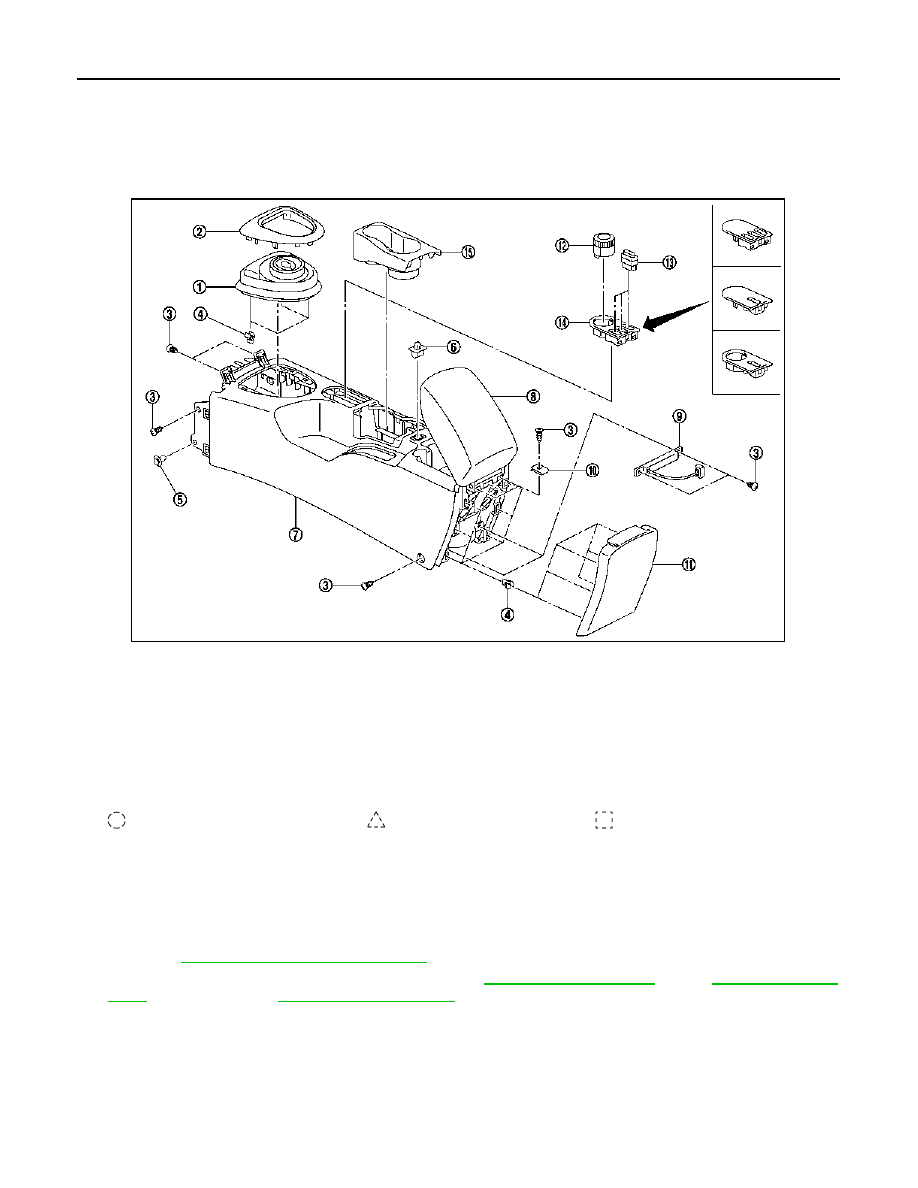
Exploded View
INFOID:0000000001093680
CENTER CONSOLE
Removal and Installation
INFOID:0000000001093681
REMOVAL
1.
Put selector lever in drive position. (CVT Models only)
2.
Remove selector lever knob. (CVT Models only)
• Refer to
TM-326, "Removal and Installation"
3.
Remove shift lever knob. (M/T Models only) Refer to
(6MT: RS6F94R),
(6MT: RS6F52A).
4.
Remove console finisher.
5.
Disconnect antenna harness connector.
6.
Remove antenna fixing screws.
7.
Remove antenna harness fixing clip.
8.
Remove center console.
INSTALLATION
1.
Console finisher assembly (M/T mod-
els)
2.
Console finisher assembly (CVT
models)
3.
Center console fixing screw
4.
Center console boot assembly fixing
clip
5.
Center console fixing clip
6.
Center console lid latch assem-
bly
7.
Center console assembly
8.
Center console lid
9.
Antenna
10. U-nut
11. Center console rear finisher as-
sembly
12. 4WD switch assembly
13. Switch (hazard, door lock, heated seat) 14. Switch panel
15. Cup holder
Clip
Pawl
Metal clip
E1JIA0017ZZ
CENTER CONSOLE ASSEMBLY
IP-19
< ON-VEHICLE REPAIR >
C
D
E
F
G
H
I
K
L
M
A
B
IP
N
O
P
Install in the reverse order of removal.
Disassembly and Assembly
INFOID:0000000001093682
Disassembly
1.
Pull upwards and then remove console rear finisher assembly.
2.
Remove GPS antenna and connector (models with Navigation). Refer to
3.
Remove cup holder.
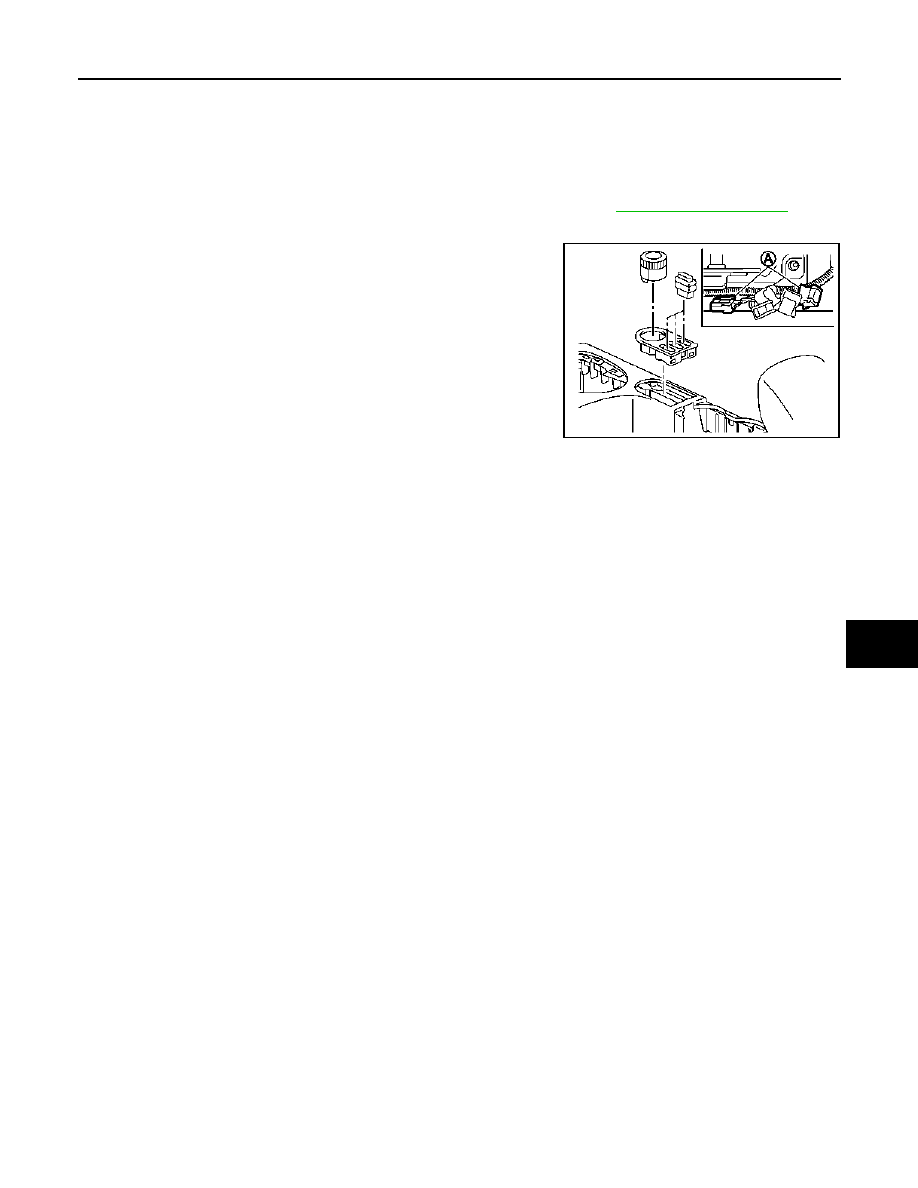
4.
Remove 4WD switch assembly and switches, then disconnect
connector (A) and remove switch panel.
5.
Remove console mask.
6.
Remove console lid.
7.
Remove metal clip and remove console rear finisher.
Assembly
Assemble in the reverse order of disassembly.
E1JIA0013ZZ
SE-1
BODY INTERIOR
C
D
E
F
G
H
I
K
L
M
SECTION
SE
A
B
SE
N
O
P
CONTENTS
SEAT
BASIC INSPECTION . . . . . . . . .
DIAGNOSIS AND REPAIR WORKFLOW . . ..
Work Flow . . . . . . . . . . . . . . . .....
FUNCTION DIAGNOSIS . . . . . . . ...
HEATED SEAT . . . . . . . . . . . . .
System Description . . . . . . . . . . . . ...
Component Parts Location . . . . . . . . . ....
Component Description . . . . . . . . . . .....
COMPONENT DIAGNOSIS . . . . . . ..
HEATED SEAT POWER SUPPLY AND
GROUND CIRCUIT . . . . . . . . . . . .
Component Function Check . . . . . . . . . ..
Diagnosis Procedure . . . . . . . . . . . .....
HEATED SEAT SWITCH . . . . . . . . .
Description . . . . . . . . . . . . . . . ....
Component Function Check . . . . . . . . . ..
Diagnosis Procedure . . . . . . . . . . . .....
Component Inspection . . . . . . . . . . . ..
SEAT HEATER . . . . . . . . . . . . .
Description . . . . . . . . . . . . . . . ....
Component Function Check . . . . . . . . . ..
Diagnosis Procedure . . . . . . . . . . . .....
Component Inspection . . . . . . . . . . . ..
HEATED SEAT . . . . . . . . . . . . .
Wiring Diagram - HEATED SEAT SYSTEM - . . ...
SYMPTOM DIAGNOSIS . . . . . . . ..
BOTH DRIVER SEAT HEATER AND PAS-
SENGER SEAT HEATER DO NOT OPERATE
.
Diagnosis Procedure . . . . . . . . . . . ...
BOTH DRIVER SEAT HEATER AND PAS-
SENGER SEAT HEATER DO NOT OPERATE
...
Diagnosis Procedure . . . . . . . . . . . ...
PASSENGER SIDE HEATER DOES NOT OP-
ERATE . . . . . . . . . . . . . . . ...
Diagnosis Procedure . . . . . . . . . . . ...
SQUEAK AND RATTLE TROUBLE DIAGNO-
SIS . . . . . . . . . . . . . . . . . .
Work Flow . . . . . . . . . . . . . . . .
Inspection Procedure . . . . . . . . . . . ...
Diagnostic Worksheet . . . . . . . . . . . ..
PRECAUTION . . . . . . . . . . . ..
PRECAUTIONS . . . . . . . . . . . . .
Service Notice . . . . . . . . . . . . . . .
Precaution for Work . . . . . . . . . . . . .
PREPARATION . . . . . . . . . . ...
PREPARATION . . . . . . . . . . . . .
Commercial Service Tool . . . . . . . . . .
ON-VEHICLE MAINTENANCE . . . . .
PRE-INSPECTION FOR DIAGNOSTIC . . .
Basic Inspection . . . . . . . . . . . . . ..
ON-VEHICLE REPAIR . . . . . . . . .
FRONT SEAT . . . . . . . . . . . . .
Exploded View . . . . . . . . . . . . . . .
Removal and Installation . . . . . . . . . . .
Нет комментариевНе стесняйтесь поделиться с нами вашим ценным мнением.
Текст