Nissan Qashqai (2007-2010). Manual — part 726
BRC-102
< COMPONENT DIAGNOSIS >
[ESP/TCS/ABS]
C1101, C1102, C1103, C1104 WHEEL SENSOR-1
YES
>> Replace applicable wheel sensor.
NO
>> Replace ABS actuator and electric unit (control unit).
Component Inspection
INFOID:0000000000924815
1.
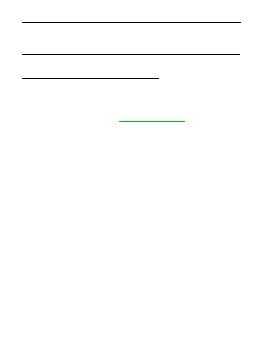
CHECK DATA MONITOR
On “DATA MONITOR”, select “FR LH SENSOR”, “FR RH SENSOR”, “RR LH SENSOR”, and “RR RH SEN-
SOR”, and check the vehicle speed.
Is the inspection result normal?
YES
>> INSPECTION END
NO
>> Go to diagnosis procedure. Refer to
BRC-100, "Diagnosis Procedure"
Special Repair Requirement
INFOID:0000000000924816
1.
ADJUSTMENT OF STEERING ANGLE SENSOR NEUTRAL POSITION
Always perform the neutral position adjustment for the steering angle sensor, when replacing the ABS actua-
tor and electric unit (control unit). Refer to
BRC-78, "ADJUSTMENT OF STEERING ANGLE SENSOR NEU-
>> END
Wheel sensor
Vehicle speed (DATA MONITOR)
FR LH SENSOR
Nearly matches the speedometer dis-
play (
±
10% or less)
FR RH SENSOR
RR LH SENSOR
RR RH SENSOR
C1105, C1106, C1107, C1108 WHEEL SENSOR-2
BRC-103
< COMPONENT DIAGNOSIS >
[ESP/TCS/ABS]
C
D
E
G
H
I
J
K
L
M
A
B
BRC
N
O
P
C1105, C1106, C1107, C1108 WHEEL SENSOR-2
Description
INFOID:0000000000977401
ABS unit continually monitors wheel speed sensors to detect abnormal signals.
DTC Logic
INFOID:0000000000924818
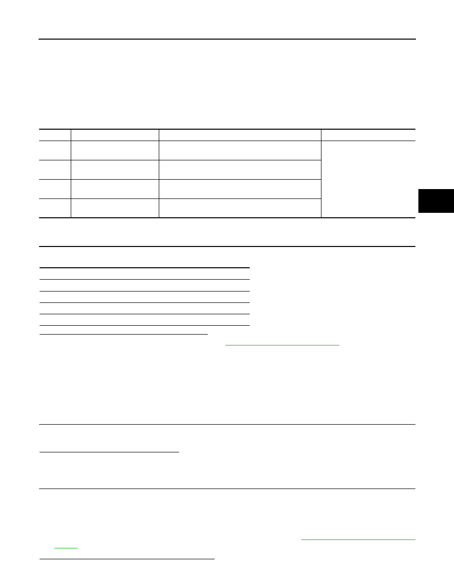
DTC DETECTION LOGIC
DTC CONFIRMATION PROCEDURE
1.
CHECK SELF-DIAGNOSIS RESULTS
Check the self-diagnosis results.
Is above displayed on the self-diagnosis display?
YES
>> Proceed to diagnosis procedure. Refer to
BRC-103, "Diagnosis Procedure"
NO
>> INSPECTION END
Diagnosis Procedure
INFOID:0000000000977403
CAUTION:
Do not check between wheel sensor terminals.
INSPECTION PROCEDURE
1.
CHECK SENSOR AND SENSOR ROTOR
• Check sensor rotor for damage.
• Check wheel sensor for damage, disconnection or looseness.
Are the sensor and sensor rotor normal?
YES
>> GO TO 2.
NO
>> Repair wheel sensor mount or replace sensor rotor. Then perform the self-diagnosis.
2.
CHECK CONNECTOR
1.
Turn ignition switch OFF.
2.
Disconnect ABS actuator and electric unit (control unit) connector.
3.
Disconnect malfunctioning wheel sensor connector.
4.
Check terminal for deformation, disconnection, looseness, and so on. If any malfunction is found, repair or
replace terminal.
5.
Reconnect connectors and then perform the self-diagnosis. Refer to
.
Is any item indicated on the self-diagnosis display?
DTC
Display item
Malfunction detected condition
Possible cause
C1105
RR RH SENSOR-2
Signal from rear RH wheel sensor does not match other
3 wheel speed signal.
• Sensor not installed corretly
• Sensor rotor or encoder dam-
aged
• Sensor rotor loose on axle
• Electrical interference
• Wheel not turning - e.g. vehi-
cle driven on 2WD dyno
• Sensor damaged
• ABS unit damaged
C1106
RR LH SENSOR-2
Signal from rear LH wheel sensor does not match other
3 wheel speed signal.
C1107
FR RH SENSOR-2
Signal from front RH wheel sensor does not match other
3 wheel speed signal.
C1108
FR LH SENSOR-2
Signal from front LH wheel sensor does not match other
3 wheel speed signal.
Self-diagnosis results
RR RH SENSOR-2
RR LH SENSOR-2
FR RH SENSOR-2
FR LH SENSOR-2

BRC-104
< COMPONENT DIAGNOSIS >
[ESP/TCS/ABS]
C1105, C1106, C1107, C1108 WHEEL SENSOR-2
YES
>> GO TO 3.
NO
>> Poor connection of connector terminal. Repair or replace connector.
3.
CHECK WHEEL SENSOR HARNESS
1.
Turn ignition switch OFF.
2.
Disconnect ABS actuator and electric unit (control unit) connector.
3.
Disconnect malfunctioning wheel sensor connector.
4.
Check continuity between terminals. (Also check continuity when steering wheel is turned right and left
and when sensor harness inside the wheel house is moved.)
Measurement terminal for power supply circuit
Measurement terminal for signal circuit
Measurement terminal for ground circuit
5.
Reconnect ABS actuator and electric unit (control unit) connector.
Is the inspection result normal?
YES
>> GO TO 4.
NO
>> Repair or replace malfunctioning components.
4.
CHECK WHEEL SENSOR POWER SUPPLY CIRCUIT
1.
Turn ignition switch ON.
2.
Check voltage between wheel sensor harness connector power supply terminal and ground.
Is the inspection result normal?
YES
>> Replace applicable wheel sensor.
NO
>> Replace ABS actuator and electric unit (control unit).
ABS actuator and electric unit (control unit)
Wheel sensor
Continuity
Connector
Terminal
Connector
Terminal
E36
9
E39 (Front RH)
2
Existed
16
E22 (Front LH)
8
B41 (Rear RH)
6
B44 (Rear LH)
ABS actuator and electric unit (control unit)
Wheel sensor
Continuity
Connector
Terminal
Connector
Terminal
E36
10
E39 (Front RH)
1
Existed
5
E22 (Front LH)
19
B41 (Rear RH)
17
B44 (Rear LH)
ABS actuator and electric unit (control unit)
Continuity
Connector
Terminal
Connector
Terminal
E36
10, 9
E36
1, 4
Not existed
5, 16
19, 8
17, 6
Wheel sensor
—
Voltage
Connector
Terminal
E39 (Front RH)
2
Ground
8 V or more
E22 (Front LH)
B41 (Rear RH)
B44 (Rear LH)

C1105, C1106, C1107, C1108 WHEEL SENSOR-2
BRC-105
< COMPONENT DIAGNOSIS >
[ESP/TCS/ABS]
C
D
E
G
H
I
J
K
L
M
A
B
BRC
N
O
P
Component Inspection
INFOID:0000000000977404
1.
CHECK DATA MONITOR
On “DATA MONITOR”, select “FR LH SENSOR”, “FR RH SENSOR”, “RR LH SENSOR”, and “RR RH SEN-
SOR”, and check the vehicle speed.
Is the inspection result normal?
YES
>> INSPECTION END
NO
>> Go to diagnosis procedure. Refer to
BRC-103, "Diagnosis Procedure"
.
Special Repair Requirement
INFOID:0000000000977405
1.
ADJUSTMENT OF STEERING ANGLE SENSOR NEUTRAL POSITION
Always perform the neutral position adjustment for the steering angle sensor, when replacing the ABS actua-
tor and electric unit (control unit). Refer to
BRC-78, "ADJUSTMENT OF STEERING ANGLE SENSOR NEU-
>> END
Wheel sensor
Vehicle speed (DATA MONITOR)
FR LH SENSOR
Nearly matches the speedometer dis-
play (
±
10% or less)
FR RH SENSOR
RR LH SENSOR
RR RH SENSOR
Нет комментариевНе стесняйтесь поделиться с нами вашим ценным мнением.
Текст