Nissan Qashqai (2007-2010). Manual — part 83
EM-280
< ON-VEHICLE REPAIR >
[K9K]
OIL PAN
OIL PAN
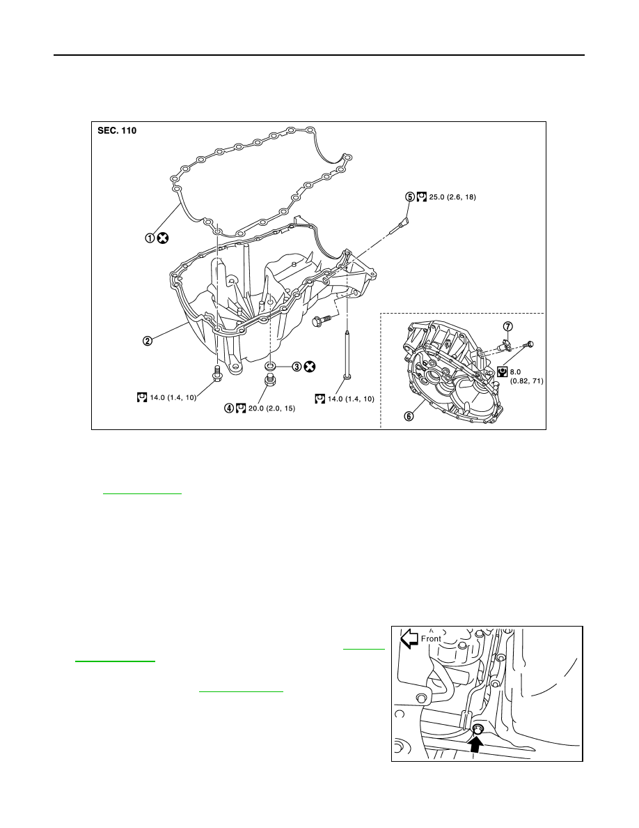
Exploded View
INFOID:0000000001060322
Removal and Installation
INFOID:0000000001060447
CAUTION:
To avoid the danger of being scalded, never drain the engine oil when the engine is hot.
REMOVAL
1.
Remove engine undercover.
2.
Remove RH front wheel.
3.
Remove right side splash cover.
4.
Remove multifunction bracket mounting bolt as shown.
5.
Remove bolts (3) from the catalyst bracket. Refer to
6.
Remove oil level sensor.
7.
Drain engine oil. Refer to
.
CAUTION:
Perform when engine is cold.
1.
Gasket
2.
Oil pan
3.
O-ring
4.
Drain plug
5.
Oil level sensor
6.
Clutch housing
7.
Crankshaft position sensor
Refer to
for symbols in the figure.
E1BIA0008GB
MBIB1038E
OIL PAN
EM-281
< ON-VEHICLE REPAIR >
[K9K]
C
D
E
F
G
H
I
J
K
L
M
A
EM
N
P
O
8.
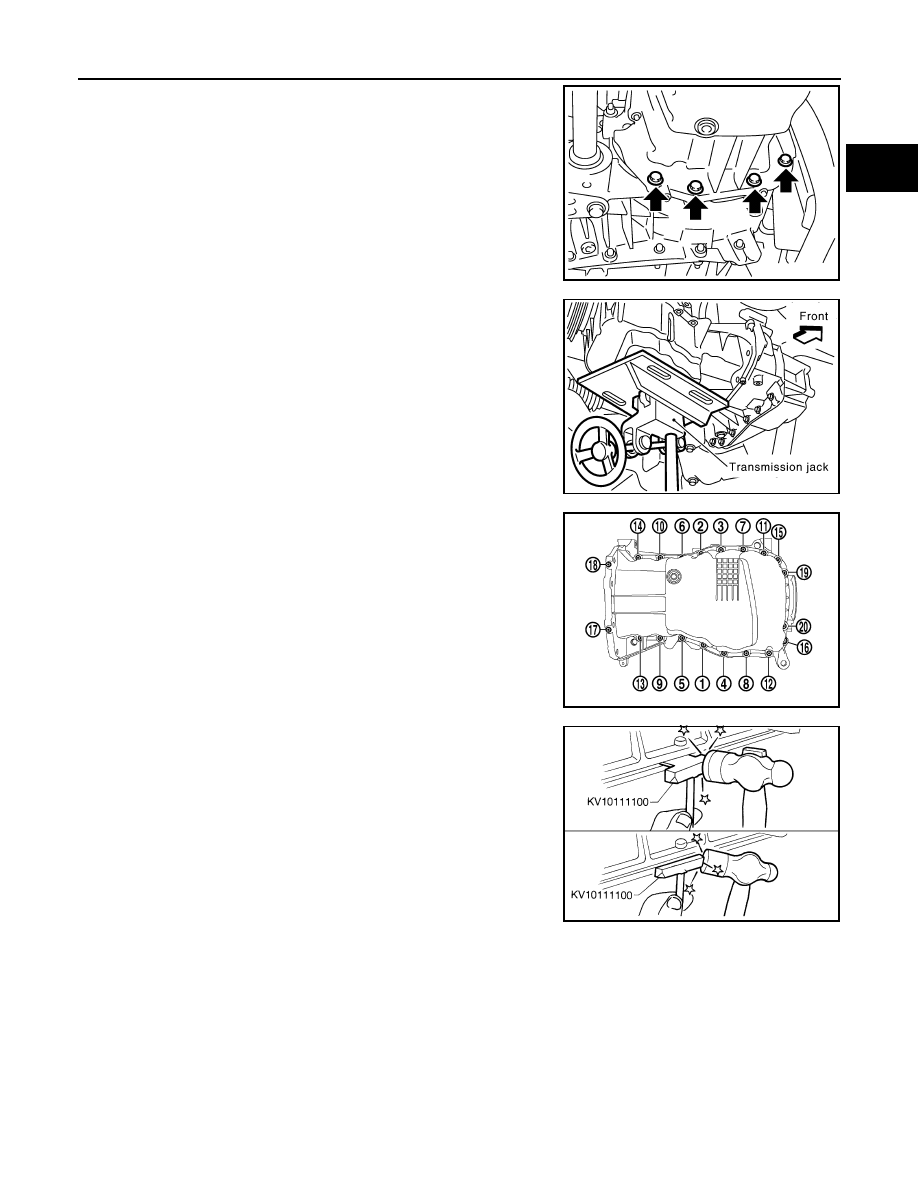
Remove oil pan and transaxle joint bolts.
9.
Support the engine bottom of the oil pan with a transmission jack
etc.
10. Remove oil pan bolt reverse order as shown.
11. Insert seal cutter [SST: KV10111100 (—)] between upper oil pan
and cylinder block. Slide tool by tapping on the side of the tool
with a hammer.
CAUTION:
Exercise care not to damage mating surface.
12. Remove oil pan.
INSTALLATION
• Install in the reverse order of removal paying attention to the following.
MBIB1039E
MBIB0575E
MBIB1257E
SEM365EA
EM-282
< ON-VEHICLE REPAIR >
[K9K]
OIL PAN
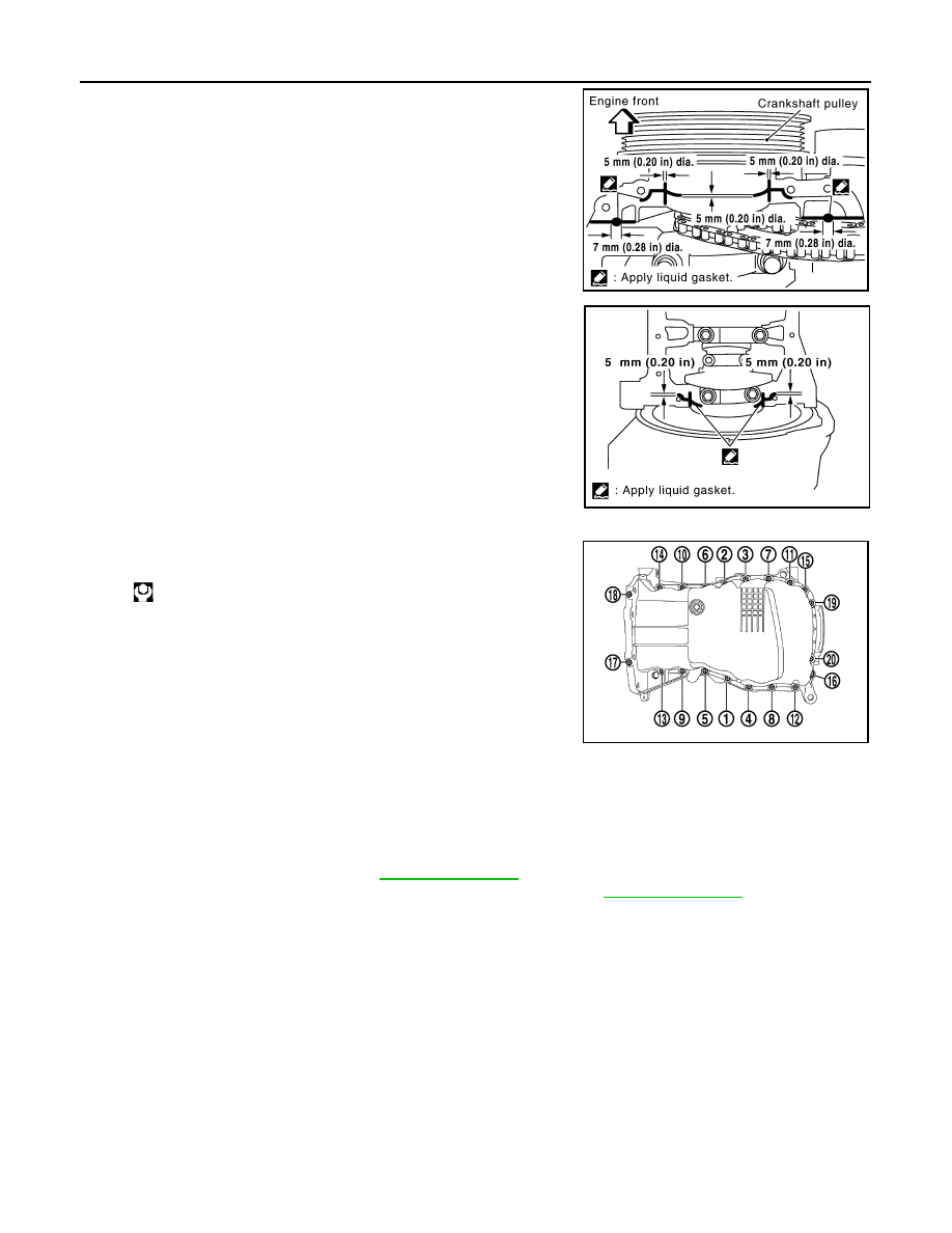
1.
Apply liquid gasket as shown.
• Use Genuine Liquid Gasket or equivalent.
2.
Using ruler, align the oil pan with the cylinder block.
3.
Install oil pan bolts in numerical order as shown.
4.
At least 30 minutes after oil pan is installed, pour engine oil.
Inspection
INFOID:0000000001060324
INSPECTION AFTER REMOVAL
Clean oil pump assembly if any object attached.
INSPECTION AFTER INSTALLATION
• Inspection the engine oil level. Refer to
.
• Start the engine, and make sure there is no leak of engine oil. Refer to
.
MBIB0593E
MBIB0594E
: 14.0 N·m (1.4 kg-m, 10 ft-lb)
MBIB1257E
HIGH PRESSURE SUPPLY PUMP
EM-283
< ON-VEHICLE REPAIR >
[K9K]
C
D
E
F
G
H
I
J
K
L
M
A
EM
N
P
O
HIGH PRESSURE SUPPLY PUMP
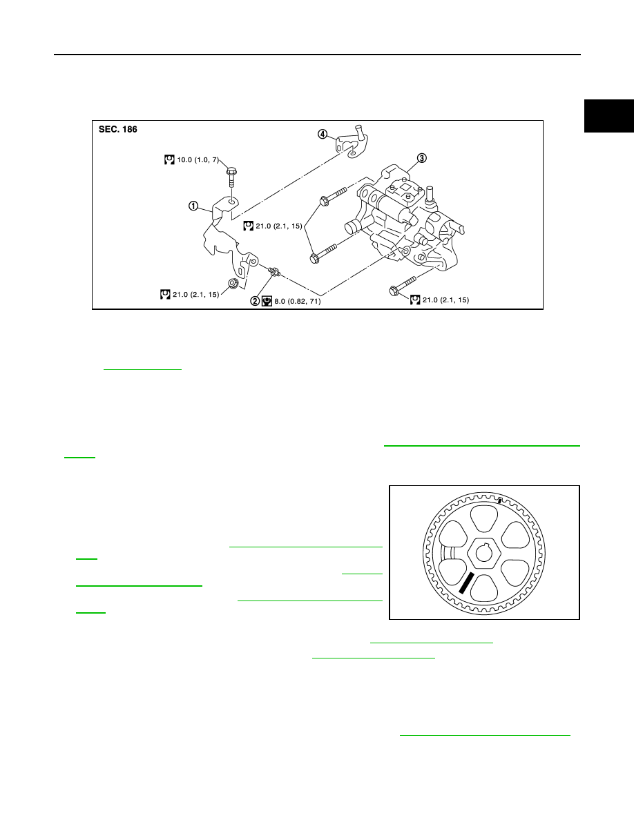
Exploded View
INFOID:0000000001060378
Removal and Installation
INFOID:0000000001060462
REMOVAL
CAUTION:
• Be sure to read “Precautions for Diesel Equipment”. Refer to
EM-249, "Precaution for Diesel Equip-
• Wait until the fuel temperature drops before carrying out any work.
• Order the special high pressure injection circuit plug kit.
• It is strictly forbidden to remove any high pressure supply
pump sprocket marked number 070 575 (see diagram). If the
pump is being replaced, the pulley must be replaced.
1.
Disconnect the battery.
2.
Remove engine cover. Refer to
EM-266, "Removal and Installa-
3.
Remove charge air cooler hose and pipes. Refer to
4.
Remove the timing belt. Refer to
.
5.
Remove the neck located on the fuel rail,
6.
Remove the oil level gauge guide and plug the hole. Refer to
.
7.
Remove high pressure protection cover. Refer to
.
8.
Carefully disconnect:
• The connectors from the flow actuator,
• The connectors from the fuel temperature sensor,
• On the pump, the fuel supply and return pipes.
• The return pipe connecting the injectors with the pump.
9.
Remove the injection tube connecting the pump to the rail. Refer to
EM-277, "Removal and Installation"
.
10. Plug all the holes of the injection circuit.
11. Remove the three mounting bolts from the high pressure supply pump then remove it.
INSTALLATION
1.
High pressure supply pump protec-
tor
2.
Stud bolt
3.
High pressure supply pump
4.
Engine cover bracket
Refer to
E1BIA0019GB
MBIB9036E
Нет комментариевНе стесняйтесь поделиться с нами вашим ценным мнением.
Текст