Nissan Qashqai (2007-2010). Manual — part 494
FL-12
< ON-VEHICLE REPAIR >
[HR16DE, MR20DE]
FUEL LEVEL SENSOR UNIT, FUEL FILTER AND FUEL PUMP ASSEMBLY
7.
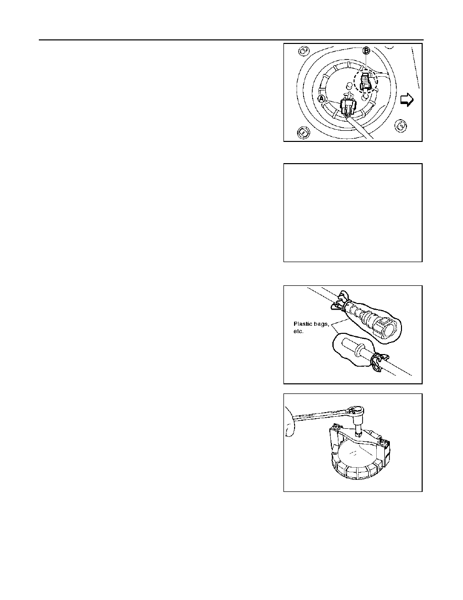
Disconnect harness connector (A) and quick connector (B).
• Remove quick connector in the following procedures.
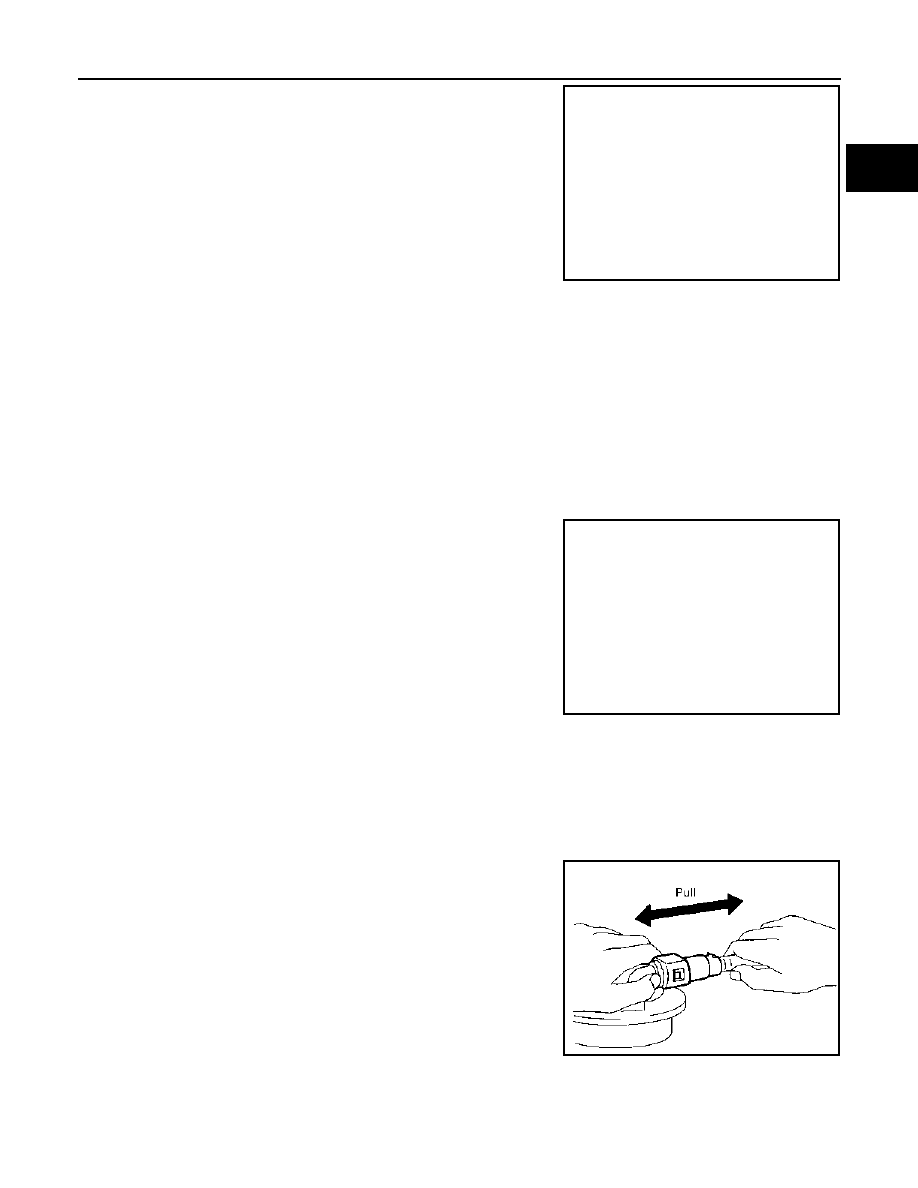
- Pinch quick connector square-part (A) with your fingers, and
pull out the quick connector by hand.
- If quick connector and tube on sender unit are stuck, push and
pull several times until they move, and pull out.
CAUTION:
• Quick connector can be removed when the tabs are
completely depressed. Never twist it more than neces-
sary.
• Never use any tools to disconnect quick connector.
• Keep resin tube away from heat. Be especially careful
when welding near the resin tube.
• Prevent acid liquid such as battery electrolyte, etc. from
getting on resin tube.
• Never bend or twist resin tube during installation and disconnection.
• To keep the connecting portion clean and to avoid dam-
age and foreign materials, cover them completely with
plastic bags or something similar.
• Never insert plug, preventing damage on o-ring in quick
connector.
8.
Using lock ring wrench (commercial service tool), remove lock
ring.
NOTE:
For reference when installing, put a matching mark on lock ring,
fuel pump assembly and fuel tank.
: Vehicle front
JPBIA0457ZZ
PBIC3779E
PBIC0713E
PBIC0240E
FUEL LEVEL SENSOR UNIT, FUEL FILTER AND FUEL PUMP ASSEMBLY
FL-13
< ON-VEHICLE REPAIR >
[HR16DE, MR20DE]
C
D
E
F
G
H
I
J
K
L
M
A
FL
N
P
O
9.
Raise fuel level sensor unit, fuel filter and fuel pump assembly
(1), and disconnect fuel tube and harness connector.
CAUTION:
• Never bend float arm during removal.
• Avoid polluting the inside by residue fuel. Draw out with
avoiding inclination by supporting with a cloth.
• Avoid impacts such as falling when handling compo-
nents.
10. Raise sub fuel level sensor assembly.
CAUTION:
• Never disassembly a fuel tube from sub fuel sensor assembly.
• Never bend float arm during removal.
• Avoid polluting the inside by residue fuel. Draw out with avoiding inclination by supporting with
a cloth.
• Avoid impacts such as falling when handling components.
INSTALLATION
Note the following, and install in the reverse order of removal.
Fuel Level Sensor Unit, Fuel Filter and Fuel Pump Assembly and Sub Fuel Level Sensor Assembly
1.
Install O-ring to fuel tank without any twist.
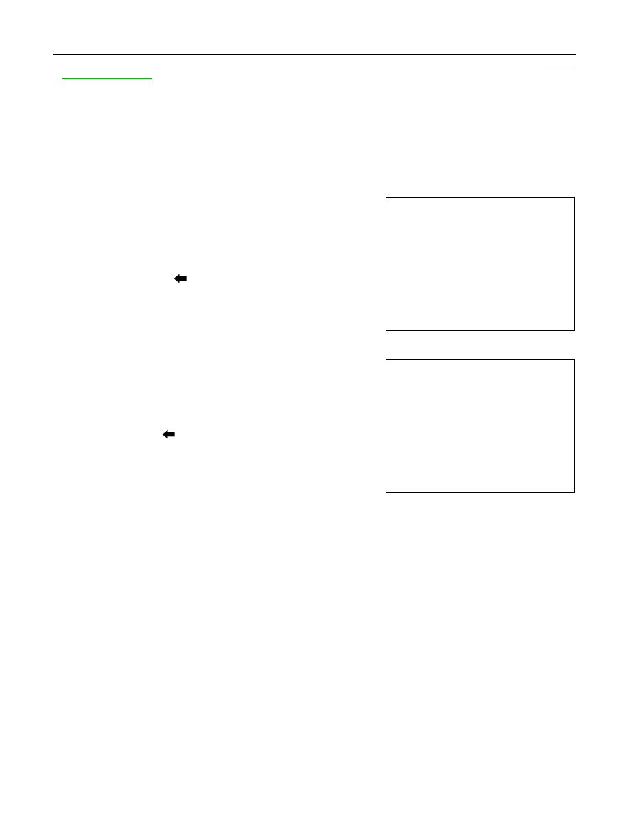
2.
Install fuel level sensor unit with aligning mating marks (A) on
fuel level sensor unit and (B) on fuel tank as shown in the figure.
NOTE:
Figure shows fuel level sensor unit, fuel filter and fuel pump
assembly side of fuel tank.
Quick Connector
Connect quick connector of fuel feed tube in the following procedures.
1.
Check the connection for damage or any foreign materials.
2.
Align the connector with the tube, then insert the connector straight into the tube until a “click” sound is
heard.
3.
After connecting, make sure that the connection is secure by following procedures.
• Visually confirm that the two tabs are connected to the connector.
• Pull the tube and the connector to make sure they are securely
connected.
4.
Connect harness connector.
Inspection Hole Cover
PBIC3780E
: Vehicle front
JPBIA0555ZZ
PBIC1653E
FL-14
< ON-VEHICLE REPAIR >
[HR16DE, MR20DE]
FUEL LEVEL SENSOR UNIT, FUEL FILTER AND FUEL PUMP ASSEMBLY
• Before installing inspection hole cover, check that the connecting part has no fuel leaks. Refer to
1.
Install inspection hole covers with the front mark (arrow) facing front of vehicle.
2.
Lock clips by turning counterclockwise.
4WD : Disassembly and Assembly
INFOID:0000000001078681
DISASSEMBLY
Fuel level sensor unit, fuel filter and fuel pump assembly side
1.
Disconnect harness connector.
2.
Remove fuel level sensor unit (1) in the following procedures.
a.
Push the pawl of fuel level sensor unit mounting area with an L-
shaped iron rod or an equivalent to unlock.
CAUTION:
Be careful not to damage fuel level sensor unit.
b.
With the fuel level sensor unit unlocked, slide it in the direction
shown by the arrow (
).
Sub fuel level sensor unit assembly side
• Remove fuel level sensor unit (1) in the following procedures.
- Push the pawl of sub fuel level sensor unit mounting area with an
L-shaped iron rod or an equivalent to unlock.
CAUTION:
Be careful not to damage sub fuel level sensor unit.
- With the sub fuel level sensor unit unlocked, slide it in the direction
shown by the arrow (
).
ASSEMBLY
Install fuel level sensor unit according to the following procedure.
• Insert until you hear a “click” sound and actually feel the engagement.
• After inserting, apply force in reverse direction (removal direction) to ensure it cannot be pulled out.
4WD : Inspection
INFOID:0000000001078682
INSPECTION AFTER INSTALLATION
Use the following procedure to check for fuel leaks.
1.
Turn ignition switch “ON” (with engine stopped), then check connections for leaks by applying fuel pres-
sure to fuel piping.
2.
Start engine and let it idle and make sure there are no fuel leaks at the fuel system connections.
PBIC4900J
JPBIA0458ZZ

FUEL TANK
FL-15
< ON-VEHICLE REPAIR >
[HR16DE, MR20DE]
C
D
E
F
G
H
I
J
K
L
M
A
FL
N
P
O
FUEL TANK
2WD
2WD : Exploded View
INFOID:0000000000905654
2WD
2WD : Removal and Installation
INFOID:0000000000905655
REMOVAL
WARNING:
Be sure to read “General Precautions” when working on the fuel system. Refer to
.
1.
Perform the steps 2 to 7 of “REMOVAL” in “ FUEL LEVEL SENSOR UNIT, FUEL FILTER AND FUEL
PUMP ASSEMBLY”. Refer to
FL-7, "2WD : Removal and Installation"
.
2.
Drain fuel from fuel tank if necessary. Refer to
FL-7, "2WD : Removal and Installation"
.
CAUTION:
• Because fuel tank forwardly inclines and becomes unstable when installing/removing, fuel
should be drained if found the remaining quantity.
• Situate vehicle on a flat and solid surface.
3.
Remove main muffler. Refer to
(HR16DE) or
(MR20DE).
1.
Fuel filler cap
2.
Grommet
3.
Fuel filler tube
4.
Cover
5.
Clamp
6.
Fuel filler hose
7.
Clamp
8.
Fuel tank band (RH)
9.
Fuel tank band (LH)
10. Protector
11.
Fuel tank
12. Vent hose
for to symbols in the figure.
JPBIA0298GB
Нет комментариевНе стесняйтесь поделиться с нами вашим ценным мнением.
Текст