Nissan Qashqai (2007-2010). Manual — part 195
COOLING FAN
EC-299
< COMPONENT DIAGNOSIS >
[HR16DE (WITH EURO-OBD)]
C
D
E
F
G
H
I
J
K
L
M
A
EC
N
P
O
YES
>> GO TO 4.
NO
>> GO TO 3.
3.
DETECT MALFUNCTIONING PART
Check the following.
• Resistor E57.
• Harness for open or short between IPDM E/R and cooling fan.
• Harness for open or short between cooling fan and ground.
• Harness for open or short between IPDM E/R and ground.
>> Repair or replace malfunctioning part.
4.
CHECK GROUND CONNECTION
1.
Turn ignition switch OFF.
2.
Check ground connection E21. Refer to Ground Inspection in
.
Is the inspection result normal?
YES
>> GO TO 5.
NO
>> Repair or replace ground connection.
5.
CHECK COOLING FAN MOTOR
EC-300, "Component Inspection (Cooling Fan Motor)"
Is the inspection result normal?
YES
>> GO TO 6.
NO
>> Replace malfunctioning cooling fan motor.
6.
CHECK INTERMITTENT INCIDENT
GI-39, "Intermittent Incident"
.
Is the inspection result normal?
YES
>> Replace IPDM E/R.
NO
>> Repair or replace harness or connector.
Component Inspection (Cooling Fan Motor)
INFOID:0000000001056498
1.
CHECK COOLING FAN MOTOR
1.
Turn ignition switch OFF.
2.
Disconnect cooling fan motor harness connector E3.
3.
Supply cooling fan motor terminals with battery voltage and check operation.
Is the inspection result normal?
YES
>> INSPECTION END
NO
>> Replace cooling fan motor.
Terminals
Operation
(+)
(–)
1
2
Cooling fan operates.
EC-300
< COMPONENT DIAGNOSIS >
[HR16DE (WITH EURO-OBD)]
ELECTRICAL LOAD SIGNAL
ELECTRICAL LOAD SIGNAL
Description
INFOID:0000000001056500
The electrical load signal (Headlamp switch signal, rear window defogger switch signal, etc.) is transferred
through the CAN communication line from BCM to ECM via IPDM E/R.
Component Function Check
INFOID:0000000001056501
1.
CHECK REAR WINDOW DEFOGGER SWITCH FUNCTION
1.
Turn ignition switch ON.
2.
Connect CONSULT-III and select “DATA MONITOR” mode.
3.
Select “LOAD SIGNAL” and check indication under the following conditions.
Is the inspection result normal?
YES
>> GO TO 2.
NO
>> Go to
2.
CHECK LIGHTING SWITCH FUNCTION
Check “LOAD SIGNAL” indication under the following conditions.
Is the inspection result normal?
YES
>> GO TO 3.
NO
>> Go to
3.
CHECK HEATER FAN CONTROL SWITCH FUNCTION
Select “HEATER FAN SW” and check indication under the following conditions.
Is the inspection result normal?
YES
>> INSPECTION END
NO
>> Go to
Diagnosis Procedure
INFOID:0000000001056502
1.
INSPECTION START
Confirm the malfunctioning circuit (rear window defogger, headlamp or heater fan). Refer to
Which circuit is related to the incident?
Rear window defogger>>GO TO 2
Headlamp>>GO TO 3.
Heater fan>>GO TO 4.
2.
CHECK REAR WINDOW DEFOGGER SYSTEM
Monitor item
Condition
Indication
LOAD SIGNAL
Rear window defogger switch
ON
ON
OFF
OFF
Monitor item
Condition
Indication
LOAD SIGNAL
Lighting switch
ON at 2nd position
ON
OFF
OFF
Monitor item
Condition
Indication
HEATER FAN SW
Heater fan control switch
ON
ON
OFF
OFF

ELECTRICAL LOAD SIGNAL
EC-301
< COMPONENT DIAGNOSIS >
[HR16DE (WITH EURO-OBD)]
C
D
E
F
G
H
I
J
K
L
M
A
EC
N
P
O
>> INSPECTION END
3.
CHECK HEADLAMP SYSTEM
>> INSPECTION END
4.
CHECK HEATER FAN CONTROL SYSTEM
GI-39, "Intermittent Incident"
.
>> INSPECTION END
EC-302
< COMPONENT DIAGNOSIS >
[HR16DE (WITH EURO-OBD)]
FUEL INJECTOR
FUEL INJECTOR
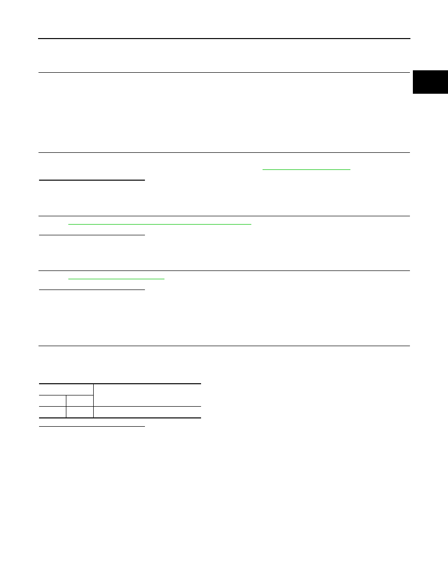
Description
INFOID:0000000001056503
The fuel injector is a small, precise solenoid valve. When the ECM
supplies a ground to the fuel injector circuit, the coil in the fuel injec-
tor is energized. The energized coil pulls the ball valve back and
allows fuel to flow through the fuel injector into the intake manifold.
The amount of fuel injected depends upon the injection pulse dura-
tion. Pulse duration is the length of time the fuel injector remains
open. The ECM controls the injection pulse duration based on
engine fuel needs.
Component Function Check
INFOID:0000000001056504
1.
INSPECTION START
Turn ignition switch to START.
Is any cylinder ignited?
YES
>> GO TO 2.
NO
>> Go to
2.
CHECK FUEL INJECTOR FUNCTION
With CONSULT-III
1.
Start engine.
2.
Perform “POWER BALANCE” in “ACTIVE TEST” mode with CONSULT-III.
3.
Make sure that each circuit produces a momentary engine speed drop.
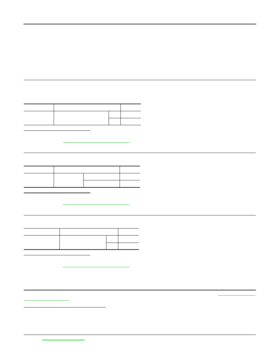
Without CONSULT-III
1.
Let engine idle.
2.
Listen to each fuel injector operating sound.
Is the inspection result normal?
YES
>> INSPECTION END
NO
>> Go to
Diagnosis Procedure
INFOID:0000000001056505
1.
CHECK FUEL INJECTOR POWER SUPPLY CIRCUIT
1.
Turn ignition switch OFF.
2.
Disconnect fuel injector harness connector.
3.
Turn ignition switch ON.
4.
Check the voltage between fuel injector harness connector and ground.
PBIA9664J
Clicking noise should be heard.
PBIB3332E
Нет комментариевНе стесняйтесь поделиться с нами вашим ценным мнением.
Текст