Nissan Qashqai (2007-2010). Manual — part 193
P2138 APP SENSOR
EC-291
< COMPONENT DIAGNOSIS >
[HR16DE (WITH EURO-OBD)]
C
D
E
F
G
H
I
J
K
L
M
A
EC
N
P
O
Check the following.
• Crankshaft position sensor (POS) (Refer to
EC-196, "Component Inspection"
• Refrigerant pressure sensor (Refer to
HAC-70, "Component Inspection"
.)
Is the inspection result normal?
YES
>> GO TO 11.
NO
>> Replace malfunctioning component.
7.
CHECK APP SENSOR GROUND CIRCUIT FOR OPEN AND SHORT
1.
Turn ignition switch OFF.
2.
Disconnect ECM harness connector.
3.
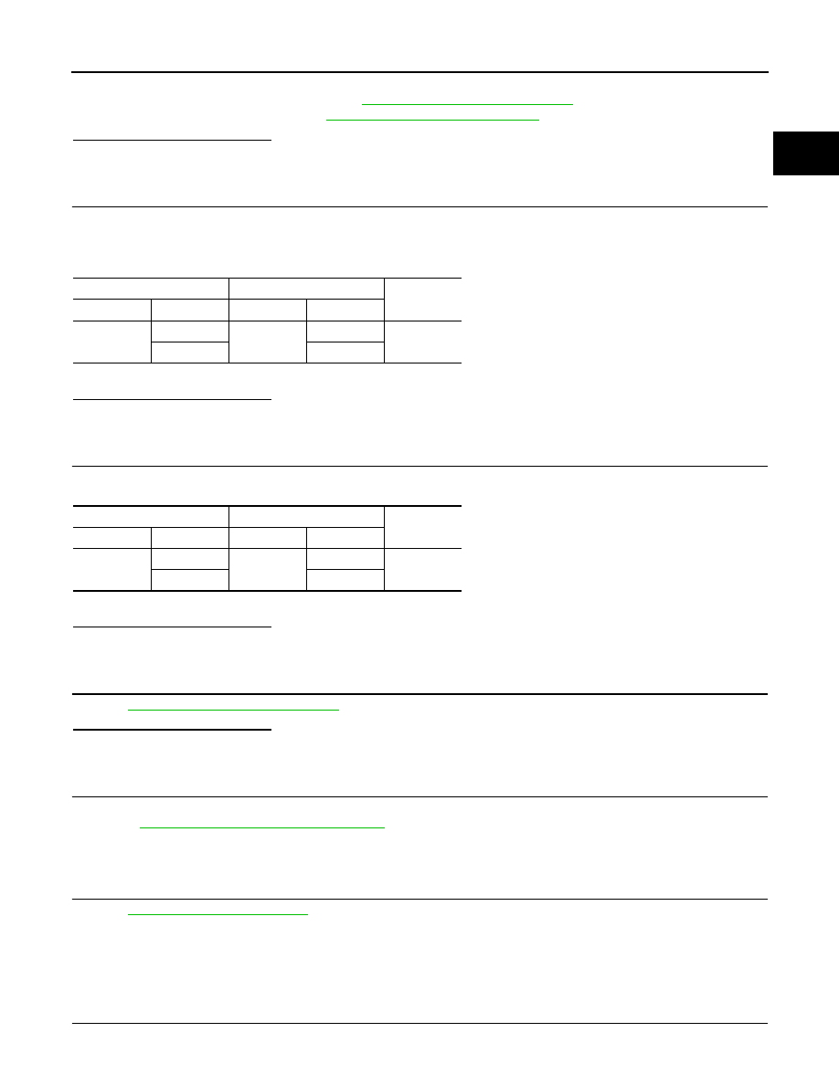
Check the continuity between APP sensor harness connector and ECM harness connector as follows.
4.
Also check harness for short to ground and short to power.
Is the inspection result normal?
YES
>> GO TO 8.
NO
>> Repair open circuit or short to ground or shot to power in harness or connectors.
8.
CHECK APP SENSOR INPUT SIGNAL CIRCUIT FOR OPEN AND SHORT
1.
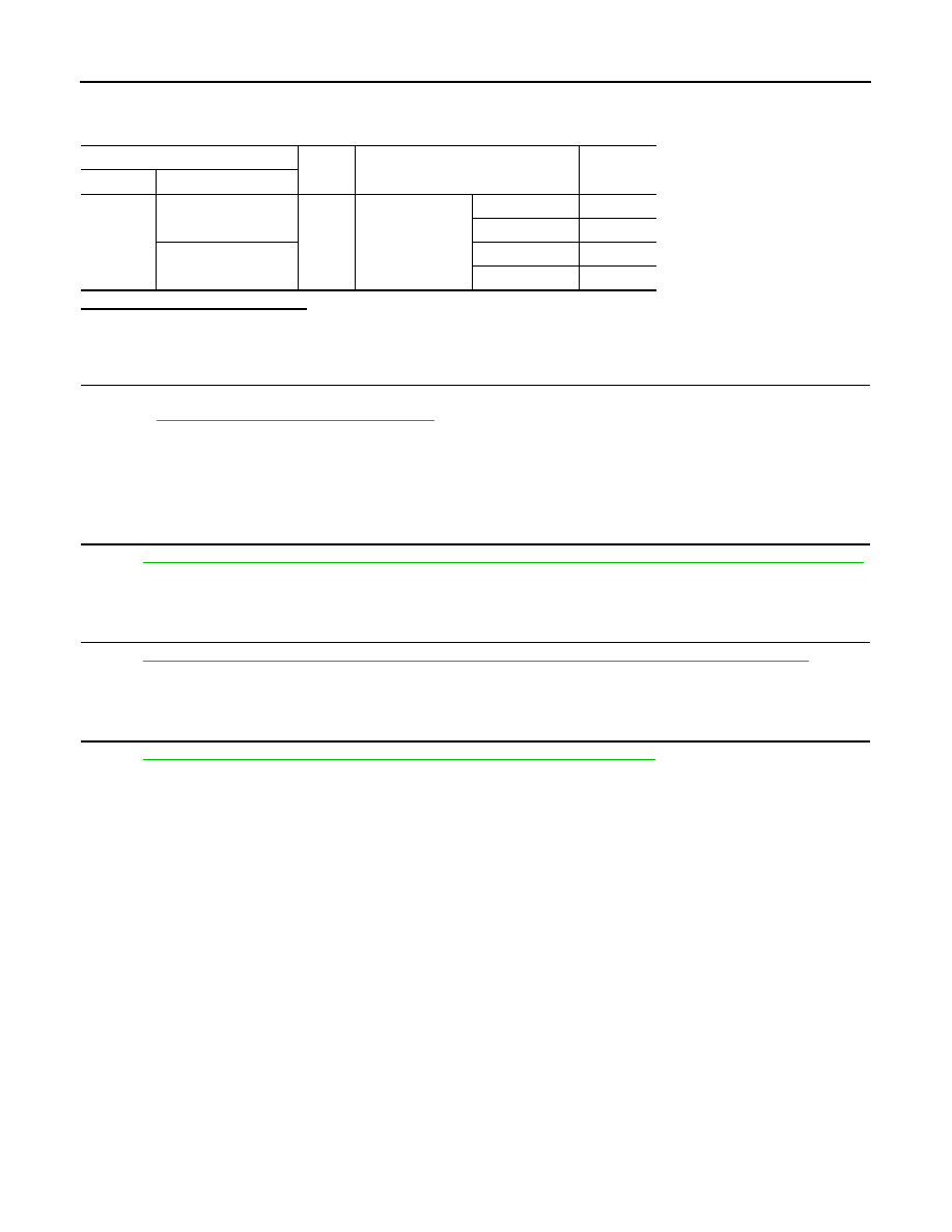
Check the continuity between APP sensor harness connector and ECM harness connector as follows.
2.
Also check harness for short to ground and short to power.
Is the inspection result normal?
YES
>> GO TO 9.
NO
>> Repair open circuit or short to ground or shot to power in harness or connectors.
9.
CHECK APP SENSOR
EC-292, "Component Inspection"
Is the inspection result normal?
YES
>> GO TO 11.
NO
>> GO TO 10.
10.
REPLACE ACCELERATOR PEDAL ASSEMBLY
1.
Replace accelerator pedal assembly.
2.
Go to
EC-293, "Special Repair Requirement"
.
>> INSPECTION END
11.
CHECK INTERMITTENT INCIDENT
GI-39, "Intermittent Incident"
.
>> INSPECTION END
Component Inspection
INFOID:0000000001056480
1.
CHECK ACCELERATOR PEDAL POSITION SENSOR
1.
Reconnect all harness connectors disconnected.
APP sensor
ECM
Continuity
Connector
Terminal
Connector
Terminal
E110
1
E16
104
Existed
2
111
APP sensor
ECM
Continuity
Connector
Terminal
Connector
Terminal
E110
3
E16
110
Existed
6
103
EC-292
< COMPONENT DIAGNOSIS >
[HR16DE (WITH EURO-OBD)]
P2138 APP SENSOR
2.
Turn ignition switch ON.
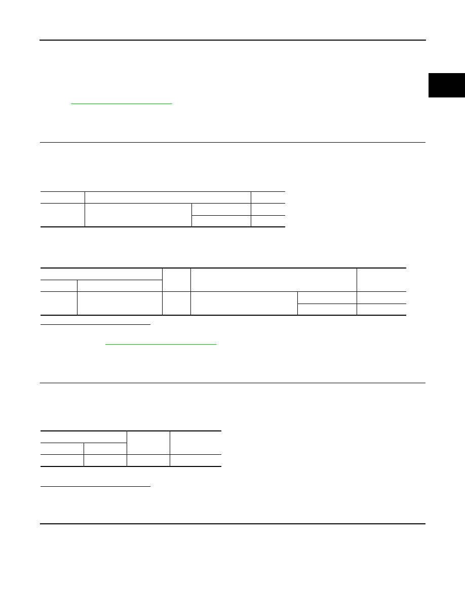
3.
Check the voltage between ECM harness connector and ground.
Is the inspection result normal?
YES
>> INSPECTION END
NO
>> GO TO 2.
2.
REPLACE ACCELERATOR PEDAL ASSEMBLY
1.
Replace accelerator pedal assembly.
2.
Go to
EC-293, "Special Repair Requirement"
.
>> INSPECTION END
Special Repair Requirement
INFOID:0000000001056481
1.
PERFORM ACCELERATOR PEDAL RELEASED POSITION LEARNING
Refer to
EC-30, "ACCELERATOR PEDAL RELEASED POSITION LEARNING : Special Repair Requirement"
.
>> GO TO 2.
2.
PERFORM THROTTLE VALVE CLOSED POSITION LEARNING
EC-31, "THROTTLE VALVE CLOSED POSITION LEARNING : Special Repair Requirement"
>> GO TO 3.
3.
PERFORM IDLE AIR VOLUME LEARNING
EC-31, "IDLE AIR VOLUME LEARNING : Special Repair Requirement"
.
>> END
ECM
Ground
Condition
Voltage
Connector
Terminal
E110
110
(APP sensor 1 signal)
Ground
Accelerator pedal
Fully released
0.6 - 0.9V
Fully depressed
3.9 - 4.7V
103
(APP sensor 2 signal)
Fully released
0.3 - 0.6V
Fully depressed
1.95 - 2.4V
ASCD BRAKE SWITCH
EC-293
< COMPONENT DIAGNOSIS >
[HR16DE (WITH EURO-OBD)]
C
D
E
F
G
H
I
J
K
L
M
A
EC
N
P
O
ASCD BRAKE SWITCH
Description
INFOID:0000000001056487
When the brake pedal is depressed, ASCD brake switch is turned OFF and stop lamp switch is turned ON.
ECM detects the state of the brake pedal by this input of two kinds (ON/OFF signal).
Refer to
for the ASCD function.
Component Function Check
INFOID:0000000001056488
1.
CHECK FOR ASCD BRAKE SWITCH FUNCTION
With CONSULT-III
1.
Turn ignition switch ON.
2.
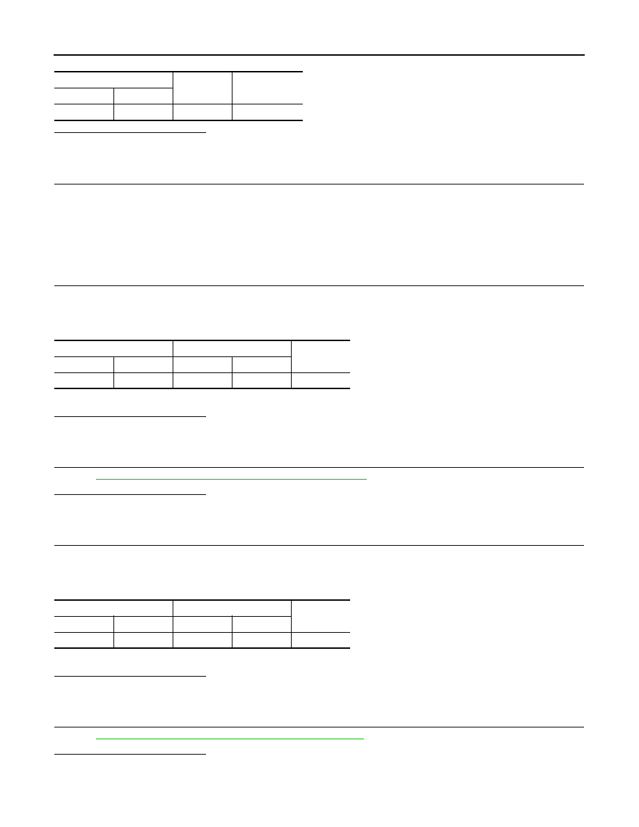
Select “BRAKE SW1” in “DATA MONITOR” mode with CONSULT-III.
3.
Check “BRAKE SW1” indication under the following conditions.
Without CONSULT-III
1.
Turn ignition switch ON.
2.
Check the voltage between ECM harness connector and ground.
Is the inspection result normal?
YES
>> INSPECTION END.
NO
>> Go to
Diagnosis Procedure
INFOID:0000000001056489
1.
CHECK ASCD BRAKE SWITCH CIRCUIT - I
1.
Turn ignition switch OFF.
2.
Disconnect ASCD brake switch harness connector.
3.
Turn ignition switch ON.
4.
Check the voltage between ASCD brake switch harness connector and ground.
5.
Also check harness for short to ground and short to power.
Is the inspection result normal?
YES
>> GO TO 6.
NO
>> GO TO 2.
2.
CHECK ASCD BRAKE SWITCH POWER SUPPLY CIRCUIT - II
1.
Turn ignition switch OFF.
2.
Disconnect ASCD clutch switch harness connector.
3.
Turn ignition switch ON.
4.
Check the voltage between ASCD clutch switch harness connector and ground.
Monitor item
Condition
Indication
BRAKE SW1
Brake pedal and clutch pedal
Slightly depressed
OFF
Fully released
ON
ECM
Ground
Condition
Voltage
Connector
Terminal
E16
100
(ASCD brake switch signal)
Ground
Brake pedal and clutch pedal
Slightly depressed
Approx. 0V
Fully released
Battery voltage
ASCD clutch switch
Ground
Voltage (V)
Connector
Terminal
E112
1
Ground
Battery voltage
EC-294
< COMPONENT DIAGNOSIS >
[HR16DE (WITH EURO-OBD)]
ASCD BRAKE SWITCH
Is the inspection result normal?
YES
>> GO TO 4.
NO
>> GO TO 3.
3.
DETECT MALFUNCTIONING PART
Check the following.
• Harness or connectors E105, M77
• 10A fuse (No. 4)
• Harness for open or short between ASCD brake switch and fuse
>> Repair open circuit or short to ground or short to power in harness or connectors.
4.
CHECK ASCD BRAKE SWITCH INPUT SIGNAL CIRCUIT FOR OPEN AND SHORT-I
1.
Turn ignition switch OFF.
2.
Check the continuity between ASCD brake switch harness connector and ASCD clutch switch harness
connector.
3.
Also check harness for short to ground and short to power.
Is the inspection result normal?
YES
>> GO TO 5.
NO
>> Repair open circuit or short to ground or short to power in harness or connectors.
5.
CHECK ASCD CLUTCH SWITCH
EC-296, "Component Inspection (ASCD Clutch Switch)"
Is the inspection result normal?
YES
>> GO TO 6.
NO
>> Replace ASCD clutch switch.
6.
CHECK ASCD BRAKE SWITCH INPUT SIGNAL CIRCUIT FOR OPEN AND SHORT-II
1.
Turn ignition switch OFF.
2.
Disconnect ECM harness connector
3.
Check the continuity between ASCD brake switch harness connector and ECM harness connector.
4.
Also check harness for short to ground and short to power.
Is the inspection result normal?
YES
>> GO TO 7.
NO
>> Repair open circuit or short to ground or short to power in harness or connectors.
7.
CHECK ASCD BRAKE SWITCH
EC-296, "Component Inspection (ASCD Brake Switch)"
.
Is the inspection result normal?
YES
>> GO TO 8.
NO
>> Replace ASCD brake switch.
ASCD clutch switch
Ground
Voltage (V)
Connector
Terminal
E111
1
Ground
Battery voltage
ASCD brake switch
ASCD clutch switch
Continuity
Connector
Terminal
Connector
Terminal
E112
1
E111
2
Existed
ASCD brake switch
ECM
Continuity
Connector
Terminal
Connector
Terminal
E112
2
E16
100
Existed
Нет комментариевНе стесняйтесь поделиться с нами вашим ценным мнением.
Текст