Nissan Qashqai (2007-2010). Manual — part 86
EM-292
< ON-VEHICLE REPAIR >
[K9K]
TIMING BELT
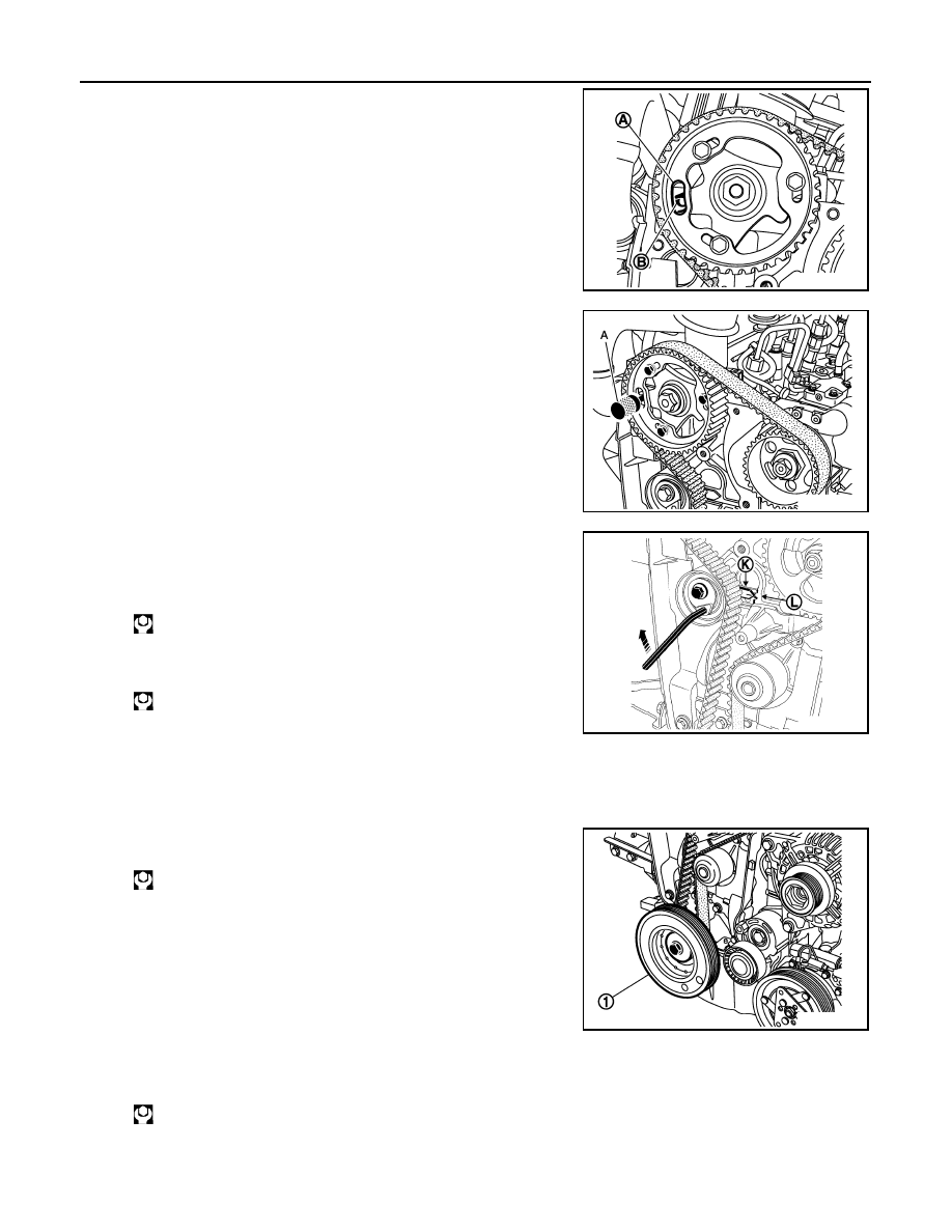
14. Turn the crankshaft two revolutions in a clockwise direction (tim-
ing side). Just before the hole (A) of the camshaft pulley is oppo-
site the cylinder head hole (B), insert TDC set pin [SST:
KV113B0130 (Mot. 1489)] into the cylinder block.
15. Then turn the crankshaft slowly and smoothly against TDC set
pin.
16. Insert TDC set pin [SST: KV113B0110 (Mot. 1430)] (A).
If the pin cannot be inserted, perform the following.
a.
Remove TDC set pin [SST: KV113B0130 (Mot. 1489)].
b.
Loosen camshaft sprocket wheel bolts.
c.
Turn camshaft pulley to adjust.
d.
Confirm that the crankshaft sprocket groove is facing upward.
e.
Loosen timing belt tensioner bolt.
f.
Move the movable index of the drive belt tensioner into the posi-
tion as shown in the figure, by turning the key clockwise.
g.
Tighten timing belt tensioner bolt.
h.
Install and tighten camshaft sprocket wheel bolts.
i.
Turn the crankshaft two revolutions in a clockwise direction (tim-
ing side). Just before the hole (A) of the camshaft pulley is opposite the cylinder head hole (B), insert TDC
set pin [SST: KV113B0130 (Mot. 1489)] into the cylinder block.
j.
Then turn the crankshaft slowly and smoothly against TDC set pin.
17. Install crankshaft pulley and tighten the bolt (1).
18. Turn bolt 95 degrees clockwise.
CAUTION:
Check and confirm the tightening angle by using the angle
wrench [SST: KV10112100 ( — )] or protractor. Avoid judg-
ment by visual inspection without the tool.
19. Remove TDC set pin [SST: KV113B0130 (Mot. 1489)] and TDC
set pin [SST: KV113B0110 (Mot. 1430)].
20. Apply liquid gasket to the thread of TDC pin plug.
21. Install TDC pin plug.
E1BIA0043ZZ
E1BIA0044ZZ
: 27.0 N·m (2.8 kg-m, 20 ft-lb)
: 14.0 N·m (1.4 kg-m, 10 ft-lb)
MBIB0511E
: 120 N·m (12 kg-m, 89 ft-lb)
: 20 N·m (2.0 kg-m, 15 ft-lb)
E1BIA0045ZZ
TIMING BELT
EM-293
< ON-VEHICLE REPAIR >
[K9K]
C
D
E
F
G
H
I
J
K
L
M
A
EM
N
P
O
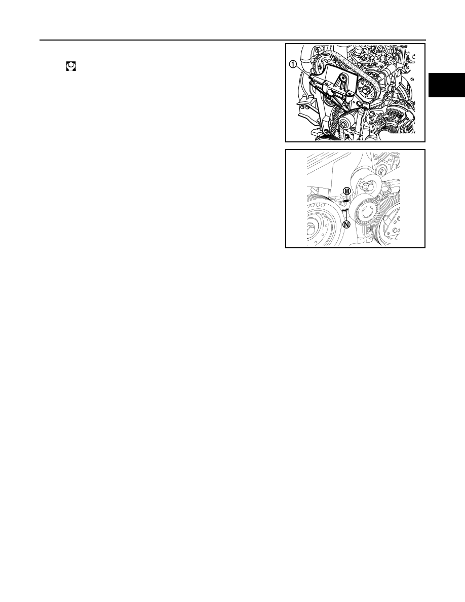
22. Install the cylinder head suspended bracket (1).
23. Install the timing cover by positioning the tab (M) into the hole
(N) on the inner timing cover.
24. Install in the reverse order of removal after this step.
: 21 N·m (2.1 kg-m, 15 ft-lb)
E1BIA0042ZZ
MBIB0514E
EM-294
< ON-VEHICLE REPAIR >
[K9K]
CAMSHAFT
CAMSHAFT
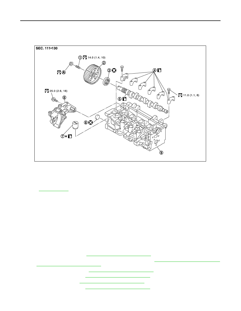
Exploded View
INFOID:0000000001060388
Removal and Installation
INFOID:0000000001060479
CAUTION:
Apply new engine oil to parts marked in illustration before installation.
REMOVAL
1.
Remove the following parts.
• Battery ground cable
• Undercover
• RH front wheel
• RH head light assembly
2.
Remove right side splash cover.
3.
Remove engine cover. Refer to
EM-287, "Removal and Installation"
.
4.
Remove air inlet tube and electric throttle control actuator. Refer to
EM-266, "Removal and Installation"
and
EM-268, "Removal and Installation"
.
5.
Remove vacuum pump. Refer to
EM-276, "Removal and Installation"
6.
Remove air inlet tube. Refer to
EM-266, "Removal and Installation"
7.
Remove drive belt. Refer to
EM-259, "Removal and Installation"
8.
Remove rocker cover. Refer to
EM-285, "Removal and Installation"
9.
Support underneath of engine by setting a manual lift table caddy (commercial service tool) or equivalent
tool.
1.
Camshaft sprocket stud bolt
2.
Camshaft sprocket
3.
Oil seal
4.
Camshaft bracket
5.
Camshaft
6.
Cylinder head suspended bracket
7.
Valve lifter
8.
Cap
9.
Cylinder head
A.
30.0 N·m (3.1 kg-m, 22 ft-lb) and 86 degrees
Refer to
for symbols in the figure.
E1BIA0023GB
CAMSHAFT
EM-295
< ON-VEHICLE REPAIR >
[K9K]
C
D
E
F
G
H
I
J
K
L
M
A
EM
N
P
O
CAUTION:
Put a piece of wood or something similar as supporting surface, secure a completely stable condi-
tion.
10. Remove timing belt. Refer to
EM-287, "Removal and Installation"
11. Remove camshaft brackets.
12. Remove camshaft.
13. Remove valve lifter.
INSTALLATION
1.
Install valve lifter.
2.
Install camshaft.
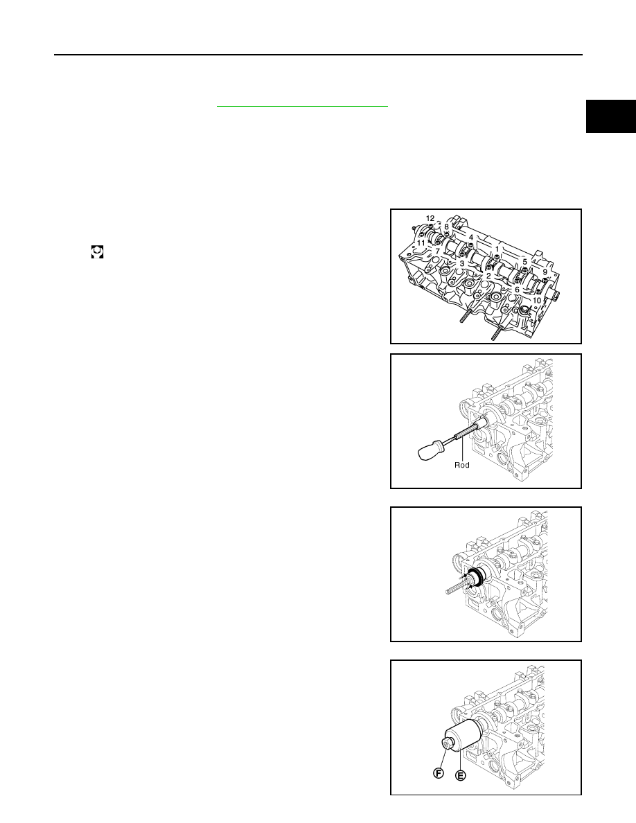
3.
Install camshaft bracket and tighten bolts in numerical order as
shown in the figure.
4.
Screw the shouldered rod of camshaft seal insert [SST:
KV113B0230 (Mot. 1632)] onto the stud of the camshaft.
5.
Install the old seal on the camshaft.
6.
For the new seal, put the protector with the seal on the cam-
shaft, taking care not to touch the seal.
7.
Install the cover (E) and the collar nut (F) of camshaft seal insert
[SST: KV113B0230 (Mot. 1632)].
: 11 N·m (1.1 kg-m, 8 ft-lb)
E1BIA0050ZZ
MBIB0430E
MBIB0431E
MBIB0432E
Нет комментариевНе стесняйтесь поделиться с нами вашим ценным мнением.
Текст