Subaru Impreza 3 / Impreza WRX / Impreza WRX STI. Service manual — part 751
EB-15
Front Hood
EXTERIOR BODY PANELS
2. Front Hood
A: REMOVAL
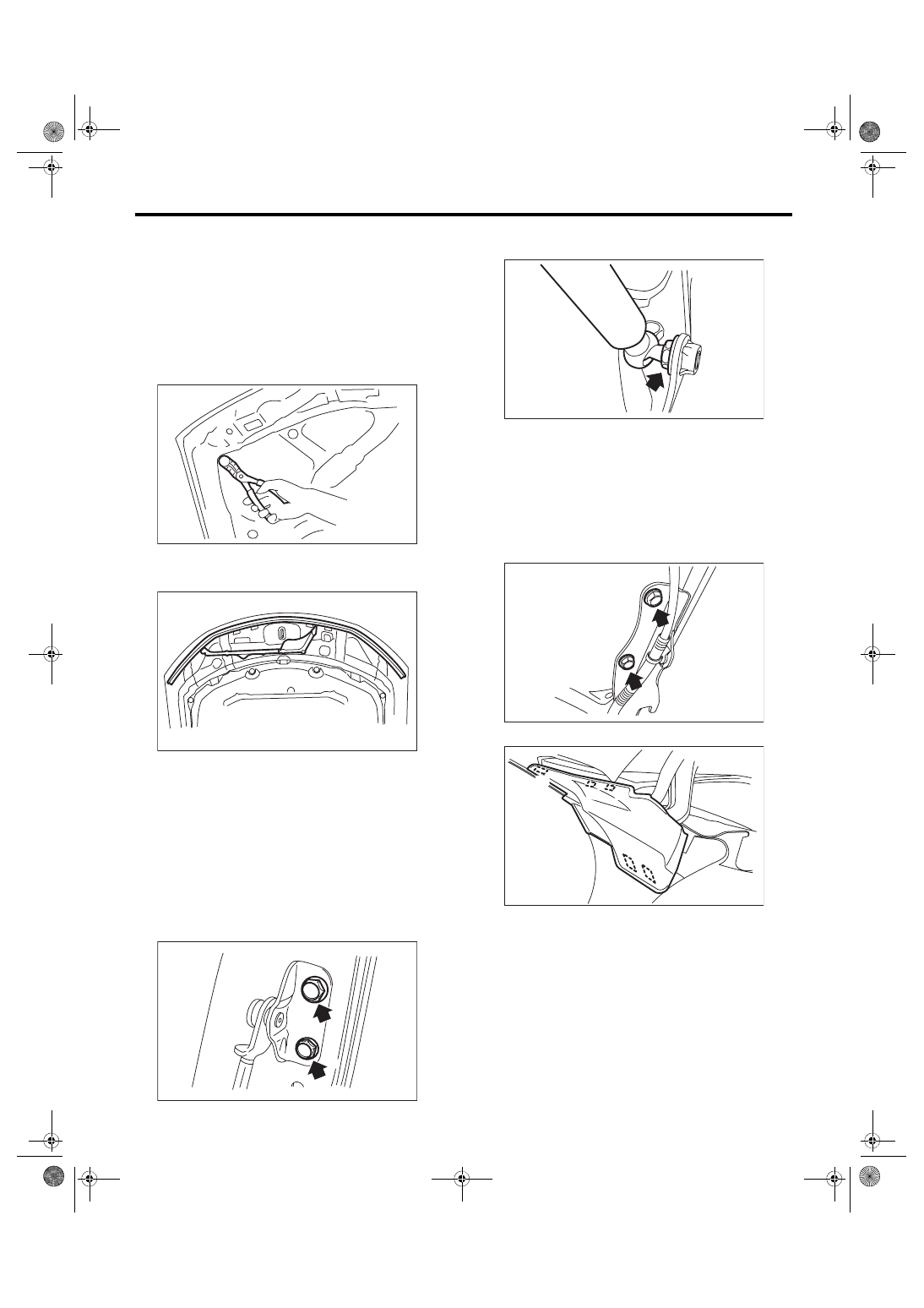
1. FRONT HOOD INSULATOR
CAUTION:
Do not reuse any clips damaged during remov-
al. Always replace with new clips.
Release the clips to remove the front hood insula-
tor.
2. FRONT HOOD SEAL
Remove the seal.
3. FRONT HOOD DAMPER
CAUTION:
• Do not damage piston rods and oil seals.
• Never disassemble cylinders: They contain
gas.
• The front hood panel is heavy. When remov-
ing or installing the damper stay and hood
hinge, be sure to work in a group of two or
more.
1) Remove mounting bolt, and remove the damper
stay.
2) Remove the mounting bolt of front hood damper
stay.
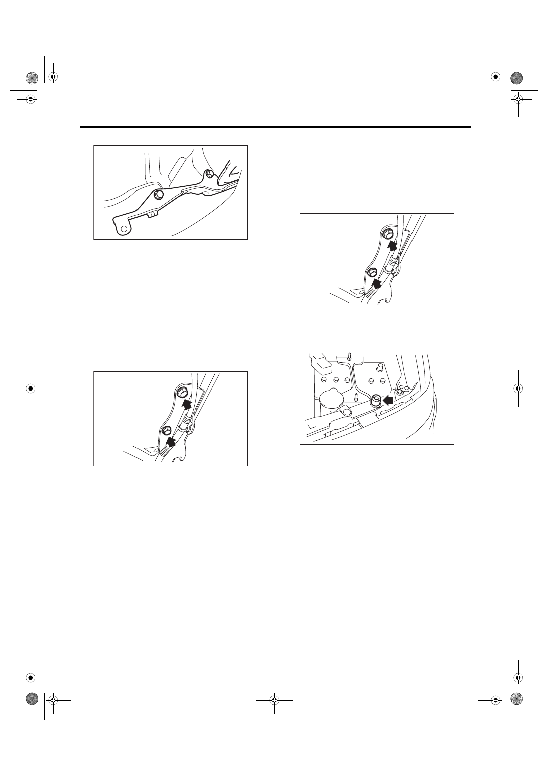
4. FRONT HOOD HINGE
CAUTION:
The front hood panel is heavy. When removing
or installing the damper stay and hood hinge,
be sure to work in a group of two or more.
1) Remove the front hood damper.
2) Remove the bolt, and remove the front hood
panel.
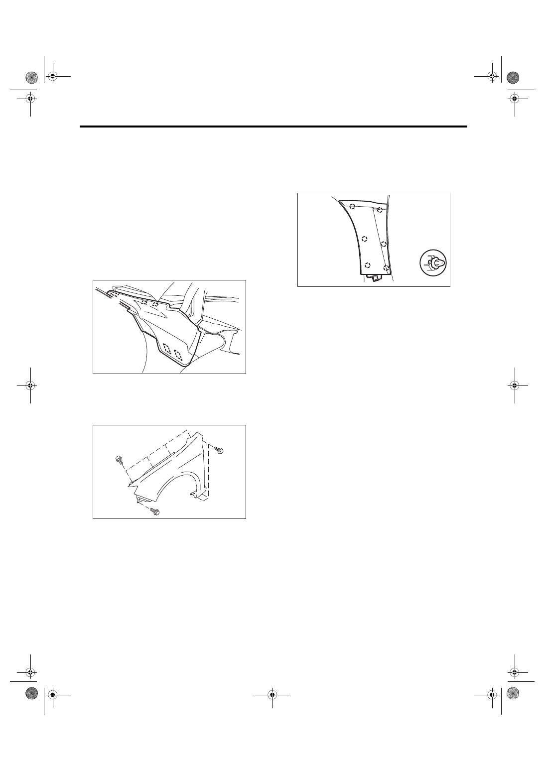
3) Detach the tabs and remove the cowl side panel.
(1) Detach tabs (A), (B), and (C) from the vehi-
cle exterior.
(2) Detach tabs (D) and (E).
EB-00291
EB-00375
EB-00383
EB-00384
EB-00385
EI-02386
(A)
(B)
(C)
(D)
(E)
EB-16
Front Hood
EXTERIOR BODY PANELS
4) Remove the bolts of front hood hinge.
5. FRONT HOOD PANEL
CAUTION:
The front hood panel is heavy. When removing
or installing the damper stay and hood hinge,
be sure to work in a group of two or more.
1) Remove the front hood insulator.
2) Remove the front hood seal.
3) Remove the window washer hose and nozzle.
<Ref. to WW-19, REMOVAL, Front Washer Noz-
4) Remove the front hood damper.
5) Remove the bolt, and remove the front hood
panel from the front hood hinge.
B: INSTALLATION
Install each part in the reverse order of removal.
NOTE:
• Be careful not to catch the window washer hose
between insulators etc.
• Install while paying attention to make a uniform
clearance around the front hood panel. For the di-
mension of clearance, refer to “SPECIFICATION”
in “General Description”. <Ref. to EB-2, SPECIFI-
CATION, General Description.>
Tightening torque:
Refer to “COMPONENT” of “General Descrip-
tion”. <Ref. to EB-8, FRONT HOOD, COMPO-
C: ADJUSTMENT
1) Adjust the clearance between front hood panel
and front fender panel. Clearance must be equal at
both sides. For the clearance dimensions, refer to
“SPECIFICATION” in “General Description”. <Ref.
to EB-2, SPECIFICATION, General Description.>
2) Use the hinge mounting bolts to align the front
hood longitudinal and lateral position.
3) Adjust the height at the front end of hood. <Ref.
to SL-39, ADJUSTMENT, Front Hood Lock Assem-
4) Rotate the hood buffer to adjust lateral height.
D: DISPOSAL
For the disposal procedures of front hood damper
stay, refer to Disposal Procedures of “Rear Gate
Damper Stay”. <Ref. to EB-32, REAR GATE
DAMPER STAY, DISPOSAL, Rear Gate.>
EB-00386
EB-00385
EB-00385
EB-00258
EB-17
Front Fender
EXTERIOR BODY PANELS
3. Front Fender
A: REMOVAL
1. FENDER PANEL
1) Disconnect the ground cable from battery.
2) Remove the side sill spoilers. <Ref. to EI-43, RE-
3) Remove the front bumper face. <Ref. to EI-31,
FRONT BUMPER FACE, REMOVAL, Front
4) Remove the headlight assembly. <Ref. to LI-15,
5) Remove the mud guard. <Ref. to EI-30, RE-
6) Detach the tabs and remove the cowl panel side.
(1) Detach tabs (A), (B), and (C) from the vehi-
cle exterior.
(2) Detach tabs (D) and (E).
7) Remove the bolt, and remove the front fender
panel.
2. COWL SIDE STAY
For operation procedures, refer to performance
stay items. <Ref. to EB-18, REMOVAL, Front Per-
3. FENDER GARNISH
1) Disconnect the ground cable from battery.
2) Remove the side sill spoilers. <Ref. to EI-43, RE-
3) Remove the clips and remove the front fender
garnish.
B: INSTALLATION
CAUTION:
• Always use new double sided tape.
• After the installation of front fender panel, be
sure to perform headlight beam adjustment.
1) Install each part in the reverse order of removal.
Tightening torque:
7.5 N·m (0.76 kgf-m, 5.5 ft-lb)
NOTE:
Install while paying attention to make a uniform
clearance around the front fender panel. For the di-
mension of clearance, refer to “SPECIFICATION”
in “General Description”. <Ref. to EB-2, SPECIFI-
2) Adjust the headlight beam and fog light beam.
• Adjust the headlight beam. <Ref. to LI-16,
HEADLIGHT BEAM ADJUSTMENT, ADJUST-
• Adjust the fog light beam. (Model with fog light)
<Ref. to LI-21, FOG LIGHT AIMING, ADJUST-
MENT, Front Fog Light Assembly.>
EI-02386
(A)
(B)
(C)
(D)
(E)
EB-00374
EB-00420
EB-18
Front Performance Stay
EXTERIOR BODY PANELS
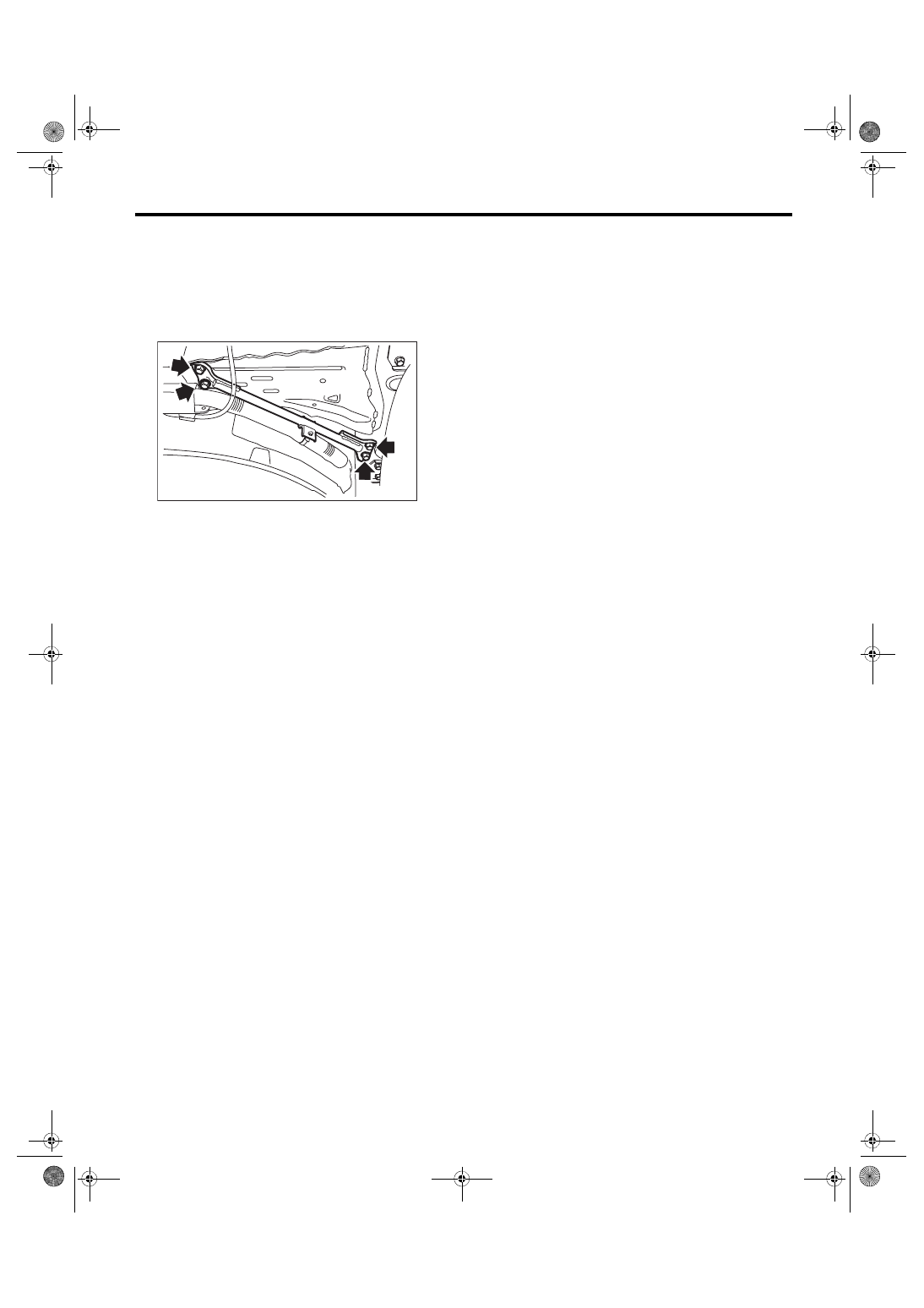
4. Front Performance Stay
A: REMOVAL
1) Remove the front fender. <Ref. to EB-17, RE-
2) Remove the bolts and harness clip, and remove
the front performance stay.
B: INSTALLATION
1) Install each part in the reverse order of removal.
Tightening torque:
70 N·m (7.14 kgf-m, 51.6 ft-lb)
NOTE:
Install while paying attention to make a uniform
clearance around the front fender panel. For the di-
mension of clearance, refer to “SPECIFICATION”
in “General Description”. <Ref. to EB-2, SPECIFI-
2) Adjust the headlight beam and fog light beam.
• Adjust the headlight beam. <Ref. to LI-16,
HEADLIGHT BEAM ADJUSTMENT, ADJUST-
• Adjust the fog light beam. (Model with fog light)
<Ref. to LI-21, FOG LIGHT AIMING, ADJUST-
MENT, Front Fog Light Assembly.>
EB-00446
Нет комментариевНе стесняйтесь поделиться с нами вашим ценным мнением.
Текст