Subaru Impreza 3 / Impreza WRX / Impreza WRX STI. Service manual — part 498
DI-37
Rear Differential (T-type)
DIFFERENTIALS
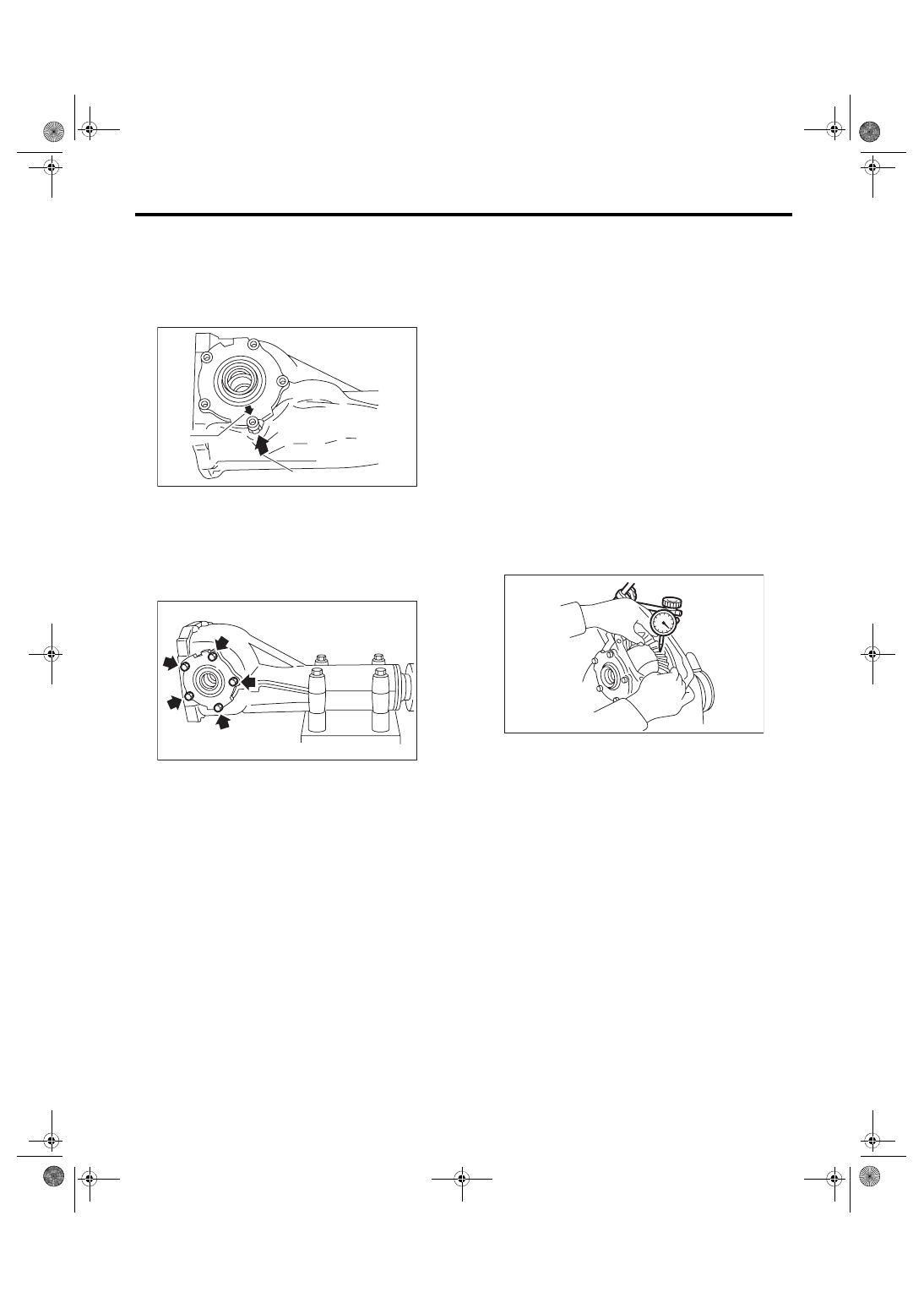
(4) Align the arrow mark on the differential car-
rier with the arrow mark on the side retainer
when installing the side retainer.
NOTE:
Be careful that the side bearing outer race is not
damaged by the bearing roller.
(5) Tighten the side retainer bolts.
Tightening torque:
10.5 N·m (1.1 kgf-m, 7.7 ft-lb)
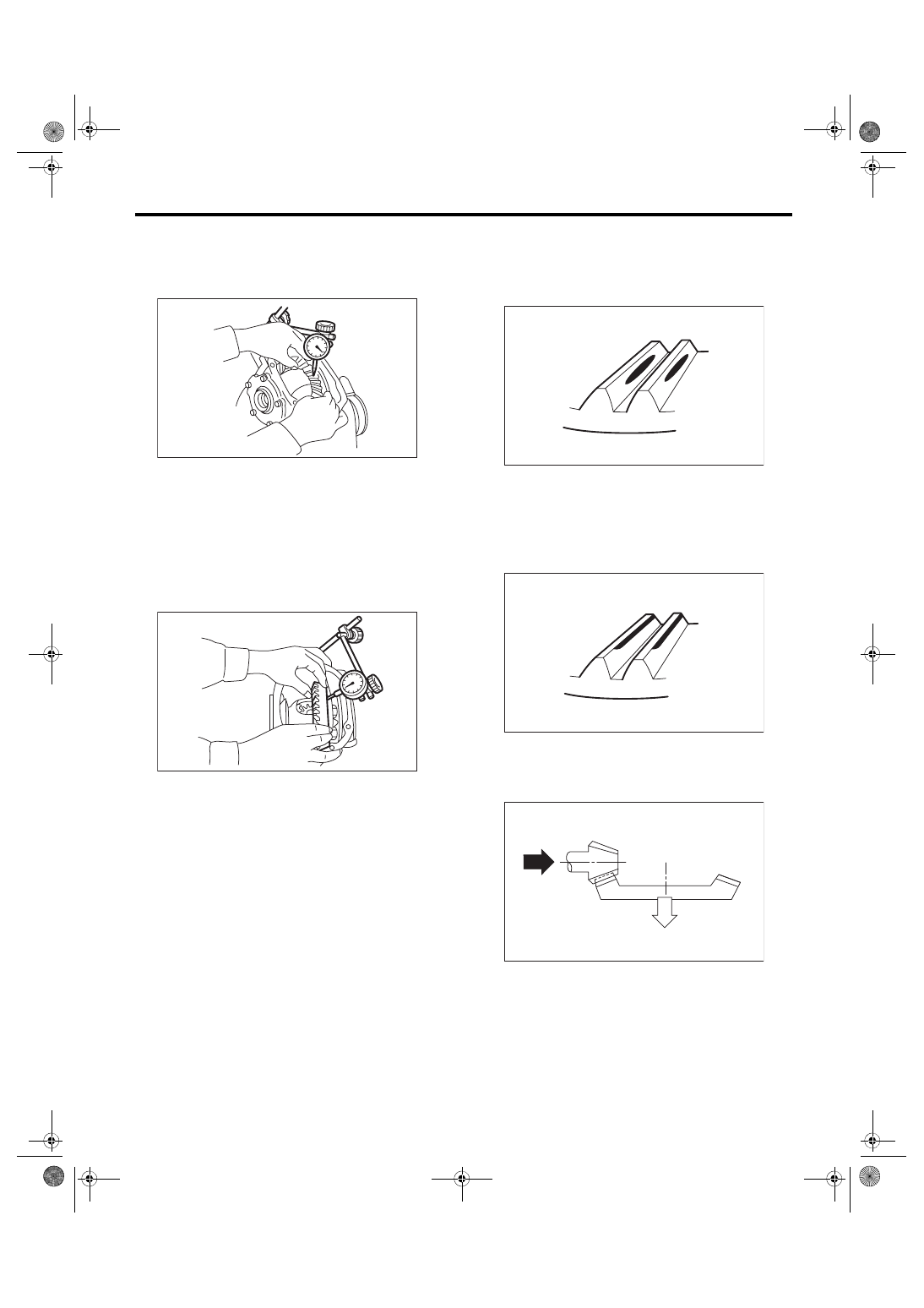
(6) Measure the hypoid driven gear to drive pin-
ion backlash. Set the magnet base on differen-
tial carrier. Align the contact point of dial gauge
with tooth face of hypoid driven gear, and move
hypoid driven gear while holding drive pinion
still. Read the value indicated on dial gauge. If
the backlash is outside the standard range, ad-
just the side retainer shim by the following
method.
• When backlash is less than 0.1 mm (0.004
in):
Reduce the thickness of shim on the back side
of the hypoid driven gear and increase the
thickness of shims on the teeth side of the hy-
poid driven gear.
• When backlash exceeds 0.2 mm (0.008 in):
Increase the thickness of shim on the back side
of the hypoid driven gear and reduce the thick-
ness of shims on the teeth side of the hypoid
driven gear.
Backlash:
0.10 — 0.20 mm (0.004 — 0.008 in)
(7) Measure the total preload of the drive pin-
ion. If the total preload is not within specifica-
tion, adjust the thickness of side retainer shims,
increasing/reducing both shims by an even
amount at a time.
Total preload:
20.7 — 54.4 N (2.1 — 5.5 kgf, 4.7 — 12.2 lbf)
(A) Arrow mark (on the side retainer)
(B) Arrow mark (on the differential carrier)
DI-00543
(B)
(A)
DI-00487
DI-00099
DI-38
Rear Differential (T-type)
DIFFERENTIALS
17) Recheck the hypoid driven gear to drive pinion
backlash.
Backlash:
0.10 — 0.20 mm (0.004 — 0.008 in)
18) Check pinion and hypoid driven gears rotate
smoothly and make sure of the hypoid driven gear
runout on its back surface. If the hypoid driven gear
runout on its back surface exceeds the specifica-
tion, check for any foreign objects between the hy-
poid driven gear and differential case, and for any
deformation of the case or gear.
Hypoid driven gear back surface runout:
0.05 mm (0.002 in)
19) Check and adjustment of the tooth contact of
hypoid driven gear and drive pinion
(1) Apply lead-free red dye evenly on the both
sides of three to four teeth of the hypoid driven
gear. Check the contact pattern after rotating
the hypoid driven gear several revolutions back
and forth until a definite contact pattern appears
on the hypoid driven gear.
(2) When the contact pattern is not correct, re-
adjust.
NOTE:
Be sure to wipe off the lead-free red dye completely
after the adjustment is completed.
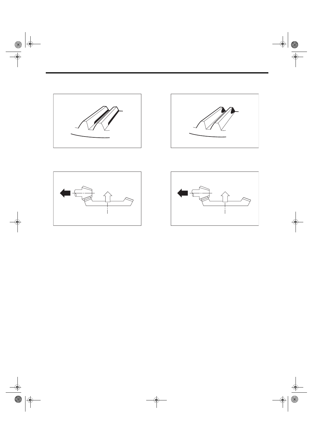
• Correct tooth contact
Check item: Tooth contact pattern is slightly
shifted toward toe side under no-load rota-
tion. (When driving, it moves towards the
heel side.)
• Face contact
Check item: Backlash is too large.
Contact pattern
Corrective action: Increase thickness of pinion
height adjusting washer according to the proce-
dure for bringing drive pinion close to hypoid
driven gear side.
DI-00099
DI-00101
(A) Toe side
(B) Heel side
(A)
(B)
MT-01401
AT-00208
AT-00212
DI-39
Rear Differential (T-type)
DIFFERENTIALS
• Flank contact
Check item: Backlash is too small.
Contact pattern
Corrective action: Reduce the thickness of pin-
ion height adjusting washer according to the
procedure for bringing drive pinion away from
hypoid driven gear.
• Toe contact (inside contact)
Check item: Teeth contact area is too small.
Contact pattern
Corrective action: Reduce the thickness of pin-
ion height adjusting washer according to the
procedure for bringing drive pinion away from
hypoid driven gear.
AT-00209
AT-00213
AT-00210
AT-00213
DI-40
Rear Differential (T-type)
DIFFERENTIALS
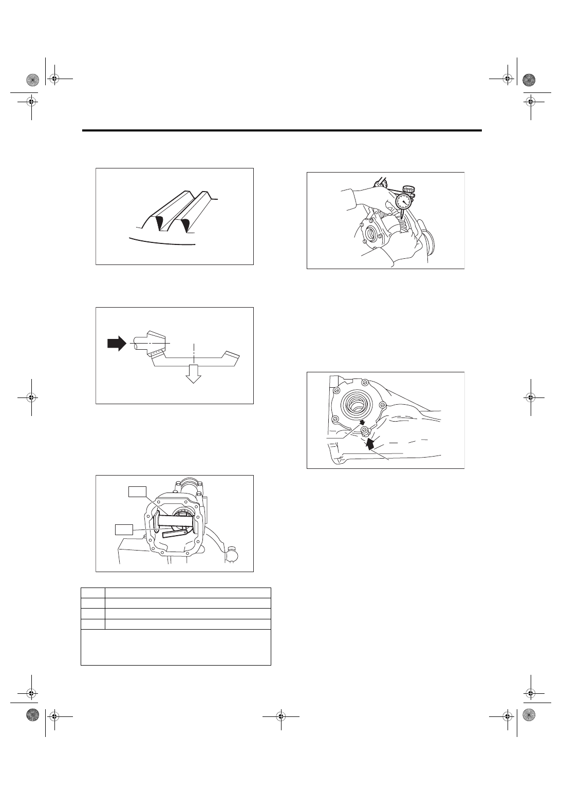
• Heel contact (outside end contact)
Check item: Teeth contact area is too small.
Contact pattern
Corrective action: Increase thickness of pinion
height adjusting washer according to the proce-
dure for bringing drive pinion close to hypoid
driven gear side.
20) If proper tooth contact is not obtained, readjust
the drive pinion height by changing the RH and LH
side retainer shims and the hypoid gear backlash.
(1) Drive pinion height
ST1 398507702
DUMMY SHAFT
ST2 398507701
DIFFERENTIAL CARRIER
GAUGE
T = To + N – (H × 0.01) – 0.20 mm (0.008 in)
(2) Hypoid gear backlash
Backlash:
0.10 — 0.20 mm (0.004 — 0.008 in)
21) Remove the RH and LH side retainers.
22) Install the O-ring to left and right side retainers.
NOTE:
Use new O-rings.
23) Install the oil seal to the side retainers on both
sides. <Ref. to DI-56, REPLACEMENT, Rear Dif-
24) Align the arrow mark on the differential carrier
with the arrow mark on the side retainer when in-
stalling the side retainer.
T
Thickness of pinion height adjusting washer mm (in)
To
Thickness of washer temporarily inserted mm (in)
N
Clearance of thickness gauge mm (in)
H
Figure marked on drive pinion head
Memo:
AT-00211
AT-00212
DI-00084
ST2
ST1
(A) Arrow mark (on the side retainer)
(B) Arrow mark (on the differential carrier)
DI-00099
DI-00543
(B)
(A)
Нет комментариевНе стесняйтесь поделиться с нами вашим ценным мнением.
Текст