Subaru Impreza 3 / Impreza WRX / Impreza WRX STI. Service manual — part 278
EN(H4DOTC)(diag)-336
Diagnostic Procedure with Diagnostic Trouble Code (DTC)
ENGINE (DIAGNOSTICS)
Step
Check
Yes
No
1
CHECK CURRENT DATA.
1) Start the engine.
2) Read the value of «TGV Position Sensor L»
using the Subaru Select Monitor.
NOTE:
Is the value of «TGV Position
Sensor L» 5 V or more?
Even if DTC is
detected, the cir-
cuit has returned to
a normal condition
at this time. Repro-
duce the failure,
and then perform
the diagnosis
again.
NOTE:
In this case, tem-
porary poor con-
tact of connector,
temporary open or
short circuit of har-
ness may be the
cause.
2
CHECK HARNESS BETWEEN ECM AND
TUMBLE GENERATOR VALVE ASSEMBLY
LH CONNECTOR.
1) Turn the ignition switch to OFF.
2) Disconnect the connector from tumble gen-
erator valve assembly LH.
3) Start the engine.
4) Read the value of «TGV Position Sensor L»
using the Subaru Select Monitor.
NOTE:
Is the value of «TGV Position
Sensor L» 5 V or more?
Repair the short
circuit to power in
harness between
ECM connector
and tumble gener-
ator valve assem-
bly LH connector.
3
CHECK HARNESS BETWEEN ECM AND
TUMBLE GENERATOR VALVE ASSEMBLY
LH CONNECTOR.
1) Turn the ignition switch to OFF.
2) Measure the resistance of harness between
tumble generator valve assembly LH connector
and engine ground.
Connector & terminal
(E51) No. 2 — Engine ground:
Is the resistance less than 5 Ω? Go to step
Repair the harness
and connector.
NOTE:
In this case, repair
the following item:
• Open circuit in
harness between
ECM
connector
and tumble gener-
ator valve assem-
bly LH connector
• Poor contact of
ECM connector
• Poor contact of
coupling connector
4
CHECK FOR POOR CONTACT.
Check for poor contact of tumble generator
valve assembly LH connector.
Is there poor contact of the tum-
ble generator valve assembly
LH connector?
Repair the poor
contact of tumble
generator valve
assembly LH con-
nector.

EN(H4DOTC)(diag)-337
Diagnostic Procedure with Diagnostic Trouble Code (DTC)
ENGINE (DIAGNOSTICS)
EC:DTC P2088 INTAKE CAMSHAFT POSITION ACTUATOR CONTROL CIRCUIT
LOW (BANK 1)
DTC DETECTING CONDITION:
• Immediately at fault recognition
• GENERAL DESCRIPTION <Ref. to GD(H4DOTC)-234, DTC P2088 INTAKE CAMSHAFT POSITION AC-
TUATOR CONTROL CIRCUIT LOW (BANK 1), Diagnostic Trouble Code (DTC) Detecting Criteria.>
TROUBLE SYMPTOM:
Improper idling
CAUTION:
After servicing or replacing faulty parts, perform Clear Memory Mode <Ref. to EN(H4DOTC)(diag)-63,
OPERATION, Clear Memory Mode.>, and Inspection Mode <Ref. to EN(H4DOTC)(diag)-49, PROCE-
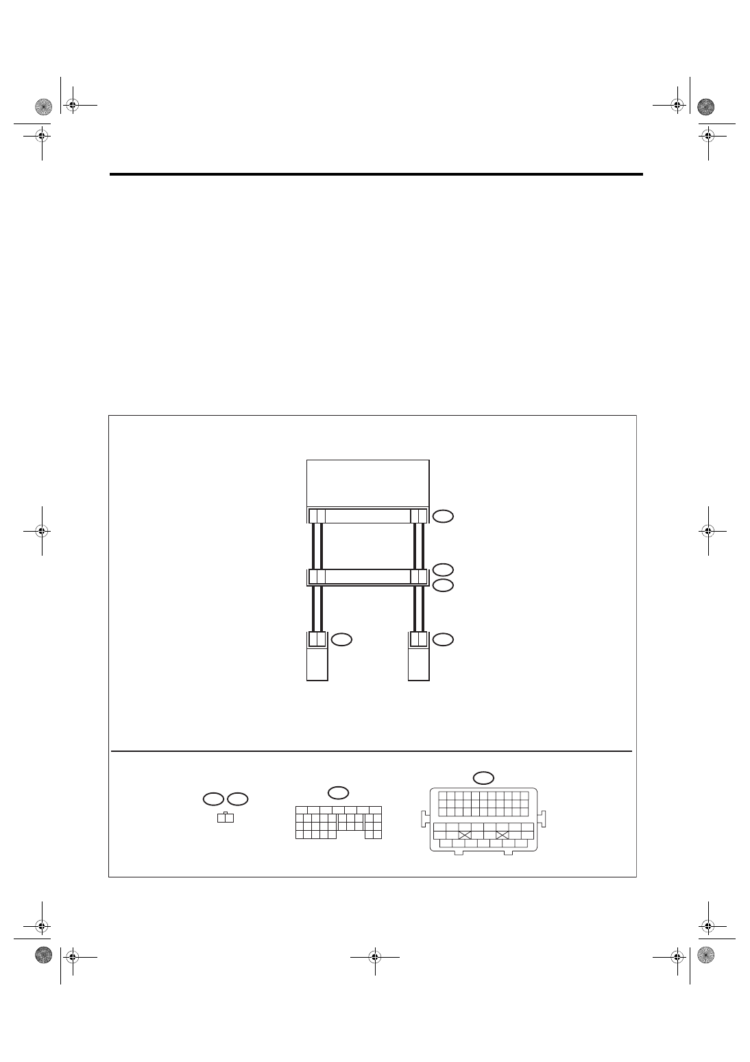
WIRING DIAGRAM:
• Engine electrical system, without SI-DRIVE <Ref. to WI-32, WITHOUT SI-DRIVE, WIRING DIAGRAM,
• Engine electrical system, with SI-DRIVE <Ref. to WI-48, WITH SI-DRIVE, WIRING DIAGRAM, Engine
ECM
E38
E37
1 2
7
1
6
1
B134
4
3
7
2
2
2
1
2
B21
E2
3
3
2
3
2
1
E38
2
1
E37
18
27
19 20 21 22 23
26
24 25
28 29
33
32
34
30 31
9
8
15
14
13
12
11
10
17
16
1
2
3
4
5
6
7
B134
15 16 17 18 19 20 21 22
23 24 25 26 27 28 29 30 31 32 33
13 14
11
12
9 10
7 8
5 6
3 4
1 2
34 35 36 37 38 39 40 41
42 43
44 45
46 47
48 49 50 51 52 53 54
B21
EN-09254
INTAKE OIL FLOW
CONTROL SOLENOID
VALVE LH
INTAKE OIL FLOW
CONTROL SOLENOID
VALVE RH

EN(H4DOTC)(diag)-338
Diagnostic Procedure with Diagnostic Trouble Code (DTC)
ENGINE (DIAGNOSTICS)
Step
Check
Yes
No
1
CHECK HARNESS BETWEEN ECM AND OIL
FLOW CONTROL SOLENOID VALVE RH
CONNECTOR.
1) Turn the ignition switch to OFF.
2) Disconnect the connectors from ECM and
oil flow control solenoid valve RH.
3) Measure the resistance of harness between
ECM connector and oil flow control solenoid
valve RH connector.
Connector & terminal
(B134) No. 34 — (E38) No. 1:
(B134) No. 27 — (E38) No. 2:
Is the resistance less than 1 Ω? Go to step
Repair the harness
and connector.
NOTE:
In this case, repair
the following item:
• Open circuit in
harness between
ECM
connector
and oil flow control
solenoid valve RH
connector
• Poor contact of
coupling connector
2
CHECK HARNESS BETWEEN ECM AND OIL
FLOW CONTROL SOLENOID VALVE RH
CONNECTOR.
Measure the resistance between ECM connec-
tor and chassis ground.
Connector & terminal
(B134) No. 34 — Chassis ground:
(B134) No. 27 — Chassis ground:
Is the resistance 1 MΩ or
more?
Repair the short
circuit to ground in
harness between
ECM connector
and oil flow control
solenoid valve RH
connector.
3
CHECK OIL FLOW CONTROL SOLENOID
VALVE.
Measure the resistance between oil flow control
solenoid valve terminals.
Terminals
No. 1 — No. 2:
Is the resistance 6 — 12 Ω?
Repair the poor
contact of ECM
and oil flow control
solenoid valve RH
connector.
EN(H4DOTC)(diag)-339
Diagnostic Procedure with Diagnostic Trouble Code (DTC)
ENGINE (DIAGNOSTICS)
ED:DTC P2089 INTAKE CAMSHAFT POSITION ACTUATOR CONTROL CIRCUIT
HIGH (BANK 1)
DTC DETECTING CONDITION:
• Immediately at fault recognition
• GENERAL DESCRIPTION <Ref. to GD(H4DOTC)-235, DTC P2089 INTAKE CAMSHAFT POSITION AC-
TUATOR CONTROL CIRCUIT HIGH (BANK 1), Diagnostic Trouble Code (DTC) Detecting Criteria.>
TROUBLE SYMPTOM:
Improper idling
CAUTION:
After servicing or replacing faulty parts, perform Clear Memory Mode <Ref. to EN(H4DOTC)(diag)-63,
OPERATION, Clear Memory Mode.>, and Inspection Mode <Ref. to EN(H4DOTC)(diag)-49, PROCE-
WIRING DIAGRAM:
• Engine electrical system, without SI-DRIVE <Ref. to WI-32, WITHOUT SI-DRIVE, WIRING DIAGRAM,
• Engine electrical system, with SI-DRIVE <Ref. to WI-48, WITH SI-DRIVE, WIRING DIAGRAM, Engine
ECM
E38
E37
1 2
7
1
6
1
B134
4
3
7
2
2
2
1
2
B21
E2
3
3
2
3
2
1
E38
2
1
E37
18
27
19 20 21 22 23
26
24 25
28 29
33
32
34
30 31
9
8
15
14
13
12
11
10
17
16
1
2
3
4
5
6
7
B134
15 16 17 18 19 20 21 22
23 24 25 26 27 28 29 30 31 32 33
13 14
11
12
9 10
7 8
5 6
3 4
1 2
34 35 36 37 38 39 40 41
42 43
44 45
46 47
48 49 50 51 52 53 54
B21
EN-09254
INTAKE OIL FLOW
CONTROL SOLENOID
VALVE LH
INTAKE OIL FLOW
CONTROL SOLENOID
VALVE RH
Нет комментариевНе стесняйтесь поделиться с нами вашим ценным мнением.
Текст