Subaru Impreza 3 / Impreza WRX / Impreza WRX STI. Service manual — part 279

EN(H4DOTC)(diag)-340
Diagnostic Procedure with Diagnostic Trouble Code (DTC)
ENGINE (DIAGNOSTICS)
Step
Check
Yes
No
1
CHECK HARNESS BETWEEN ECM AND OIL
FLOW CONTROL SOLENOID VALVE RH
CONNECTOR.
1) Turn the ignition switch to OFF.
2) Disconnect the connectors from ECM and
oil flow control solenoid valve RH.
3) Measure the voltage between ECM connec-
tor and chassis ground.
Connector & terminal
(B134) No. 34 (+) — Chassis ground (–):
(B134) No. 27 (+) — Chassis ground (–):
Is the voltage less than 1 V?
Repair the short
circuit to power in
harness between
ECM connector
and oil flow control
solenoid valve RH
connector.
2
CHECK HARNESS BETWEEN ECM AND OIL
FLOW CONTROL SOLENOID VALVE RH
CONNECTOR.
Measure the resistance of harness between
ECM connector and oil flow control solenoid
valve RH connector.
Connector & terminal
(B134) No. 34 — (E38) No. 1:
(B134) No. 27 — (E38) No. 2:
Is the resistance less than 1 Ω? Go to step
Repair the harness
and connector.
NOTE:
In this case, repair
the following item:
• Open circuit in
harness between
ECM
connector
and oil flow control
solenoid valve RH
connector
• Poor contact of
coupling connector
3
CHECK OIL FLOW CONTROL SOLENOID
VALVE.
Measure the resistance between oil flow control
solenoid valve terminals.
Terminals
No. 1 — No. 2:
Is the resistance 6 — 12 Ω?
Repair the poor
contact of ECM
and oil flow control
solenoid valve RH
connector.
EN(H4DOTC)(diag)-341
Diagnostic Procedure with Diagnostic Trouble Code (DTC)
ENGINE (DIAGNOSTICS)
EE:DTC P2090 EXHAUST CAMSHAFT POSITION ACTUATOR CONTROL CIR-
CUIT LOW (BANK 1)
DTC DETECTING CONDITION:
• Immediately at fault recognition
• GENERAL DESCRIPTION <Ref. to GD(H4DOTC)-236, DTC P2090 EXHAUST CAMSHAFT POSITION
ACTUATOR CONTROL CIRCUIT LOW (BANK 1), Diagnostic Trouble Code (DTC) Detecting Criteria.>
TROUBLE SYMPTOM:
Improper idling
CAUTION:
After servicing or replacing faulty parts, perform Clear Memory Mode <Ref. to EN(H4DOTC)(diag)-63,
OPERATION, Clear Memory Mode.>, and Inspection Mode <Ref. to EN(H4DOTC)(diag)-49, PROCE-
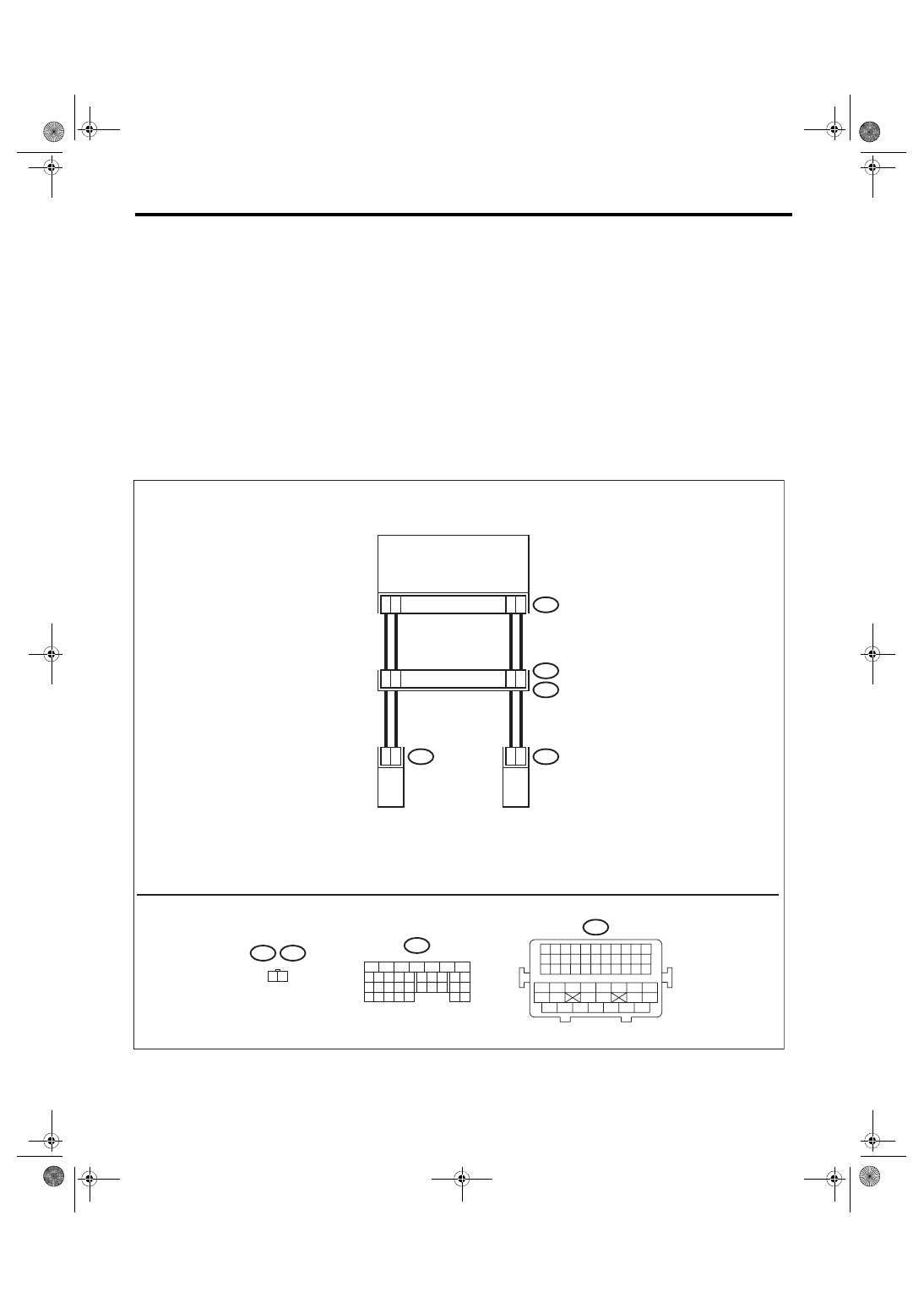
WIRING DIAGRAM:
Engine electrical system, with SI-DRIVE <Ref. to WI-48, WITH SI-DRIVE, WIRING DIAGRAM, Engine Elec-
ECM
E66
E63
1 2
5
14
B134
7
15
17
7
B21
E2
43
42
2
1
E63
2
1
E66
18
27
19 20 21 22 23
26
24 25
28 29
33
32
34
30 31
9
8
15
14
13
12
11
10
17
16
1
2
3
4
5
6
7
B134
15 16 17 18 19 20 21 22
23 24 25 26 27 28 29 30 31 32 33
13 14
11
12
9 10
7 8
5 6
3 4
1 2
34 35 36 37 38 39 40 41
42 43
44 45
46 47
48 49 50 51 52 53 54
B21
EN-09255
EXHAUST OIL FLOW
CONTROL
SOLENOID VALVE LH
EXHAUST OIL FLOW
CONTROL
SOLENOID VALVE RH

EN(H4DOTC)(diag)-342
Diagnostic Procedure with Diagnostic Trouble Code (DTC)
ENGINE (DIAGNOSTICS)
Step
Check
Yes
No
1
CHECK HARNESS BETWEEN ECM AND OIL
FLOW CONTROL SOLENOID VALVE RH
CONNECTOR.
1) Turn the ignition switch to OFF.
2) Disconnect the connectors from ECM and
oil flow control solenoid valve RH.
3) Measure the resistance of harness between
ECM connector and oil flow control solenoid
valve RH connector.
Connector & terminal
(B134) No. 7 — (E63) No. 1:
(B134) No. 15 — (E63) No. 2:
Is the resistance less than 1 Ω? Go to step
Repair the harness
and connector.
NOTE:
In this case, repair
the following item:
• Open circuit in
harness between
ECM
connector
and oil flow control
solenoid valve RH
connector
• Poor contact of
coupling connector
2
CHECK HARNESS BETWEEN ECM AND OIL
FLOW CONTROL SOLENOID VALVE RH
CONNECTOR.
Measure the resistance between ECM connec-
tor and chassis ground.
Connector & terminal
(B134) No. 7 — Chassis ground:
(B134) No. 15 — Chassis ground:
Is the resistance 1 MΩ or
more?
Repair the short
circuit to ground in
harness between
ECM connector
and oil flow control
solenoid valve RH
connector.
3
CHECK OIL FLOW CONTROL SOLENOID
VALVE.
Measure the resistance between oil flow control
solenoid valve terminals.
Terminals
No. 1 — No. 2:
Is the resistance 6 — 12 Ω?
Repair the poor
contact of ECM
and oil flow control
solenoid valve RH
connector.

EN(H4DOTC)(diag)-343
Diagnostic Procedure with Diagnostic Trouble Code (DTC)
ENGINE (DIAGNOSTICS)
EF:DTC P2091 EXHAUST CAMSHAFT POSITION ACTUATOR CONTROL CIR-
CUIT HIGH (BANK 1)
DTC DETECTING CONDITION:
• Immediately at fault recognition
• GENERAL DESCRIPTION <Ref. to GD(H4DOTC)-237, DTC P2091 EXHAUST CAMSHAFT POSITION
ACTUATOR CONTROL CIRCUIT HIGH (BANK 1), Diagnostic Trouble Code (DTC) Detecting Criteria.>
TROUBLE SYMPTOM:
Improper idling
CAUTION:
After servicing or replacing faulty parts, perform Clear Memory Mode <Ref. to EN(H4DOTC)(diag)-63,
OPERATION, Clear Memory Mode.>, and Inspection Mode <Ref. to EN(H4DOTC)(diag)-49, PROCE-
WIRING DIAGRAM:
Engine electrical system, with SI-DRIVE <Ref. to WI-48, WITH SI-DRIVE, WIRING DIAGRAM, Engine Elec-
ECM
E66
E63
1 2
5
14
B134
7
15
17
7
B21
E2
43
42
2
1
E63
2
1
E66
18
27
19 20 21 22 23
26
24 25
28 29
33
32
34
30 31
9
8
15
14
13
12
11
10
17
16
1
2
3
4
5
6
7
B134
15 16 17 18 19 20 21 22
23 24 25 26 27 28 29 30 31 32 33
13 14
11
12
9 10
7 8
5 6
3 4
1 2
34 35 36 37 38 39 40 41
42 43
44 45
46 47
48 49 50 51 52 53 54
B21
EN-09255
EXHAUST OIL FLOW
CONTROL
SOLENOID VALVE LH
EXHAUST OIL FLOW
CONTROL
SOLENOID VALVE RH
Нет комментариевНе стесняйтесь поделиться с нами вашим ценным мнением.
Текст