Subaru Impreza 3 / Impreza WRX / Impreza WRX STI. Service manual — part 266

EN(H4DOTC)(diag)-288
Diagnostic Procedure with Diagnostic Trouble Code (DTC)
ENGINE (DIAGNOSTICS)
30
CHECK HARNESS BETWEEN ECM AND
ELECTRONIC THROTTLE CONTROL CON-
NECTOR.
1) Turn the ignition switch to OFF.
2) Disconnect the connector from ECM.
3) Measure the resistance between ECM con-
nectors.
Connector & terminal
(B134) No. 19 — (B134) No. 18:
(B134) No. 19 — (B134) No. 28:
Is the resistance 1 MΩ or
more?
Repair the short
circuit to power in
the harness
between ECM con-
nector and elec-
tronic throttle
control connector.
31
CHECK SENSOR OUTPUT.
1) Connect all connectors.
2) Turn the ignition switch to ON.
3) Read the value of «Main-Throttle Sensor»
using Subaru Select Monitor.
NOTE:
Is the value of «Main-Throttle
Sensor» 0.81 — 0.87 V?
32
CHECK SENSOR OUTPUT.
Read the value of «Sub-Throttle Sensor» using
Subaru Select Monitor.
NOTE:
Is the value of «Sub-Throttle
Sensor» 1.64 — 1.70 V?
33
CHECK HARNESS BETWEEN ECM AND
ELECTRONIC THROTTLE CONTROL MO-
TOR.
1) Turn the ignition switch to OFF.
2) Disconnect the connectors from ECM and
electronic throttle control.
3) Measure the resistance between ECM con-
nector and electronic throttle control connector.
Connector & terminal
(B134) No. 2 — (E57) No. 2:
(B134) No. 1 — (E57) No. 1:
Is the resistance less than 1 Ω? Go to step
Repair the harness
and connector.
NOTE:
In this case, repair
the following item:
• Open circuit in
harness between
ECM
connector
and
electronic
throttle
control
connector
• Poor contact of
coupling connector
34
CHECK HARNESS BETWEEN ECM AND
ELECTRONIC THROTTLE CONTROL MO-
TOR.
1) Connect the connector to ECM.
2) Turn the ignition switch to ON.
3) Measure the voltage between electronic
throttle control connector and engine ground.
Connector & terminal
(E57) No. 2 (+) — Engine ground (–):
(E57) No. 1 (+) — Engine ground (–):
Is the voltage 5 V or more?
Repair the short
circuit to power in
the harness
between ECM con-
nector and elec-
tronic throttle
control connector.
Step
Check
Yes
No

EN(H4DOTC)(diag)-289
Diagnostic Procedure with Diagnostic Trouble Code (DTC)
ENGINE (DIAGNOSTICS)
CY:DTC P050B COLD START IGNITION TIMING PERFORMANCE
NOTE:
For the diagnostic procedure, refer to DTC P050A. <Ref. to EN(H4DOTC)(diag)-280, DTC P050A COLD
START IDLE AIR CONTROL SYSTEM PERFORMANCE, Diagnostic Procedure with Diagnostic Trouble
35
CHECK HARNESS BETWEEN ECM AND
ELECTRONIC THROTTLE CONTROL MO-
TOR.
1) Turn the ignition switch to OFF.
2) Disconnect the connector from ECM.
3) Measure the resistance between electronic
throttle control connector and engine ground.
Connector & terminal
(E57) No. 2 — Engine ground:
(E57) No. 1 — Engine ground:
Is the resistance 1 MΩ or
more?
Repair the ground
short circuit of har-
ness between
ECM connector
and electronic
throttle control
connector.
36
CHECK ELECTRONIC THROTTLE CON-
TROL MOTOR HARNESS.
Measure the resistance between electronic
throttle control connectors.
Connector & terminal
(E57) No. 2 — (E57) No. 1:
Is the resistance 1 MΩ or
more?
Repair the short
circuit in harness
between ECM con-
nector and elec-
tronic throttle
control connector.
37
CHECK ELECTRONIC THROTTLE CON-
TROL GROUND CIRCUIT.
Measure the resistance between ECM connec-
tor and chassis ground.
Connector & terminal
(B134) No. 3 — Chassis ground:
(B134) No. 4 — Chassis ground:
(B134) No. 6 — Chassis ground:
(B137) No. 1 — Chassis ground:
(B137) No. 3 — Chassis ground:
Is the resistance less than 5 Ω? Go to step
Repair the harness
and connector.
NOTE:
In this case, repair
the following item:
• Open circuit of
harness between
ECM
connector
and engine ground
• Poor contact of
coupling connector
38
CHECK ELECTRONIC THROTTLE CON-
TROL.
Measure the resistance between electronic
throttle control terminals.
Terminals
No. 1 — No. 2:
Is the resistance 50 Ω or less? Go to step
39
CHECK ELECTRONIC THROTTLE CON-
TROL.
Move the throttle valve to the fully open and fully
closed positions with fingers.
Check that the valve returns to the specified
position when releasing fingers.
Does the valve return to the
specified position? Standard
value: 3 mm (0.12 in) from fully
closed position
Repair the poor
contact of ECM
connector.
Step
Check
Yes
No
EN(H4DOTC)(diag)-290
Diagnostic Procedure with Diagnostic Trouble Code (DTC)
ENGINE (DIAGNOSTICS)
CZ:DTC P0560 SYSTEM VOLTAGE
DTC DETECTING CONDITION:
• Immediately at fault recognition
• GENERAL DESCRIPTION <Ref. to GD(H4DOTC)-190, DTC P0560 SYSTEM VOLTAGE, Diagnostic
Trouble Code (DTC) Detecting Criteria.>
CAUTION:
After servicing or replacing faulty parts, perform Clear Memory Mode <Ref. to EN(H4DOTC)(diag)-63,
OPERATION, Clear Memory Mode.>, and Inspection Mode <Ref. to EN(H4DOTC)(diag)-49, PROCE-
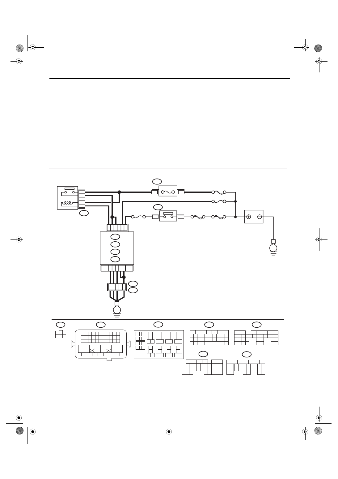
WIRING DIAGRAM:
• Engine electrical system, without SI-DRIVE <Ref. to WI-32, WITHOUT SI-DRIVE, WIRING DIAGRAM,
• Engine electrical system, with SI-DRIVE <Ref. to WI-48, WITH SI-DRIVE, WIRING DIAGRAM, Engine
ECM
EN-08715
B136
C:
B72
C1
D7
B13
A3
A6
C2 C30
24
23
22
21
B134
B135
A:
C: B136
D: B137
B:
35
34
40
A4
D3
36
B134
B135
B137
B21
B72
A:
B:
D:
D1
3
1
15A
B220
B220
B220
3
4
18
19
6
7
4
3
5
2
1
12
11
10
9
8
40
36 39
38
37
34
33
35
32
28 31
30
29
23
22
21
20
26
25
24
27
17
16
15
14
13
2
6
5
4
3
1
54
52 53
50 51
48 49
46 47
45
44
42 43
40 41
38 39
36 37
34 35
33
32
31
30
29
28
27
26
25
24
23
22
21
20
11
10
9
19
18
17
16
8
7
6
5
15
14
13
12
4
3
2
1
31
30
29
28
27
21
20
19
18
17
16
26
25
24
15
14
13
12
11
23
22
10
3
4
9
1
2
8
7
6
5
35
34
33
32
31
30
29
21
20
19
18
17
16
28
27
26
15
14
13
12
11
25
23
22
24
10
3
4
9
1
2
8
7
6
5
31
30
32
29
34
33
21
20
19
18
17
16
28
27
26
15
14
13
12
11
25
23
22
24
10
3
4
9
1
2
8
7
6
5
B21
E2
35
27
16
10 11 12 13 14 15
25
24
30
9
8
7
17 18 19 20
28
21 22 23
29
32
31
1
2
3
4
5
6
26
33 34
E
E
SBF-7
SBF-6
FUSE
(RELAY BLOCK)
IGNITION
SWITCH
BATTERY
MAIN RELAY
No. 13
No. 12
MAIN SBF

EN(H4DOTC)(diag)-291
Diagnostic Procedure with Diagnostic Trouble Code (DTC)
ENGINE (DIAGNOSTICS)
Step
Check
Yes
No
1
CHECK INPUT SIGNAL OF ECM.
1) Turn the ignition switch to OFF.
2) Measure the voltage between ECM connec-
tor and chassis ground.
Connector & terminal
(B136) No. 2 (+) — Chassis ground (–):
Is the voltage 10 V or more?
Repair the poor
contact of ECM
connector.
2
CHECK HARNESS BETWEEN ECM AND
MAIN FUSE BOX CONNECTOR.
1) Disconnect the connector from ECM.
2) Measure the resistance between ECM con-
nector and chassis ground.
Connector & terminal
(B136) No. 2 — Chassis ground:
Is the resistance 1 MΩ or
more?
Repair the short
circuit to ground in
harness between
ECM connector
and battery termi-
nal.
3
CHECK FUSE NO. 13.
Is the fuse blown out?
Replace the fuse. Repair the harness
and connector.
NOTE:
In this case, repair
the following item:
• Open circuit in
harness between
ECM
connector
and battery
• Poor contact of
ECM connector
• Poor contact of
battery terminal
Нет комментариевНе стесняйтесь поделиться с нами вашим ценным мнением.
Текст