Subaru Impreza 3 / Impreza WRX / Impreza WRX STI. Service manual — part 622
AB(diag)-27
Subaru Select Monitor
AIRBAG SYSTEM (DIAGNOSTICS)
3. DISPLAY OF STATUS INFORMATION
Check the operating condition of each sensor in the event of malfunction in the seat belt buckle switch, or
when the seat belt buckle switch has been replaced.
1) On «Main Menu» display, select {Each System Check}.
2) On «System Selection Menu» display, select {Airbag System}.
3) On «Airbag System» display, select {Status Data}.
The following table is for support data.
*1: Displayed when it is initial.
*2: Seat position sensor not supported
*3: Seat belt fastened
*4: Seat belt not fastened
*5: Displayed when data other than belt fastened or not fastened, such as breakdowns is input.
*6: Seat belt buckle switch not supported
*7: Passenger’s airbag operating state
*8: Passenger’s airbag non-operating state
NOTE:
For detailed operation procedures, refer to “PC application help for Subaru Select Monitor”.
Item
Display
Seat position sensor LH
––
*2
Seat position sensor RH
––
*2
Seat belt buckle switch LH
––
*6
Seat belt buckle switch RH
Equipped
*3
/Unequipped
*4
/Other
*5
/Initial setting
*1
/––
*6
Passenger’s airbag control status
ON
*7
/OFF
*8
/Initial setting
*1
AB(diag)-28
Subaru Select Monitor
AIRBAG SYSTEM (DIAGNOSTICS)
B: INSPECTION
1. COMMUNICATION FOR INITIALIZING IMPOSSIBLE
DETECTING CONDITION:
Defective harness connector
TROUBLE SYMPTOM:
Communication is impossible between the airbag control module and the Subaru Select Monitor.
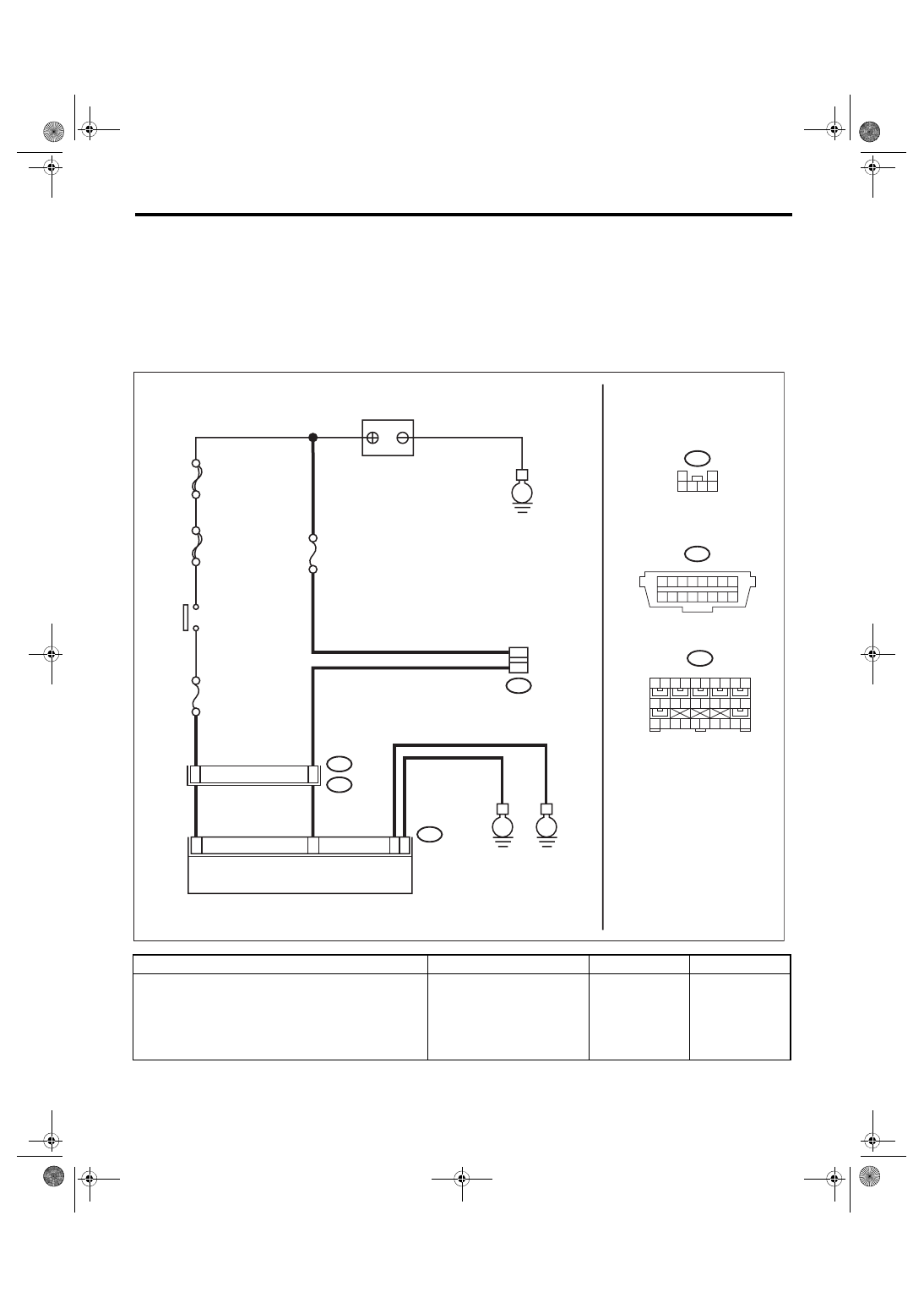
WIRING DIAGRAM:
Airbag system <Ref. to WI-82, WIRING DIAGRAM, Airbag System.>
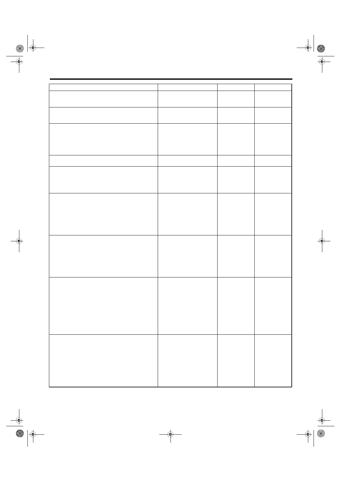
Step
Check
Yes
No
1
CHECK IGNITION SWITCH.
Is the ignition switch ON?
Turn the ignition
switch to ON, and
select the airbag
mode using the
Subaru Select
Monitor.
1 2 3 4 5 6 7 8
9 10 11 12 13 14 15 16
MAIN SBF
SBF-6
No.25
B40
B31
AB1
E
16
7
No.13
DATA LINK
CONNECTOR
BATTERY
IGNITION
SWITCH
3
AB6
E
E
16
26
25
21
AIRBAG CONTROL MODULE
B40
AB6
AB-02103
18 19 20
21 22 23 24 25 26 27 28
1 2 3
5 6 7 8
10
9
4
11 12 13 14
16 17
15
29 30
B31
1
2
3 4 5 6
1
AB(diag)-29
Subaru Select Monitor
AIRBAG SYSTEM (DIAGNOSTICS)
2
CHECK BATTERY.
1) Turn the ignition switch to OFF.
2) Measure the battery voltage.
Is the voltage 11 V or more?
Charge or replace
the battery.
3
CHECK BATTERY TERMINAL.
Is there poor contact at battery
terminal?
Repair or tighten
the battery termi-
nal.
4
CHECK SUBARU SELECT MONITOR COM-
MUNICATION.
1) Turn the ignition switch to ON.
2) Using the Subaru Select Monitor, check
whether communication to other systems can
be executed normally.
Is the system name displayed
on Subaru Select Monitor?
5
CHECK SUBARU SELECT MONITOR.
Is Subaru Select Monitor pow-
ered on?
6
CHECK FUSE.
Remove fuse No. 13 from the fuse & relay box,
and perform visual inspection.
Is the fuse OK?
Repair the harness
between the bat-
tery and the data
link connector.
Replace the fuse. If
the fuse is blown
out again, check
the power supply
circuit.
7
CHECK AIRBAG CONTROL MODULE CON-
NECTOR.
1) Turn the ignition switch to OFF, disconnect
the battery ground cable, and wait for 60 sec-
onds or more.
2) Confirm that the connectors of airbag con-
trol module (AB6, AB17, AB18) are securely
connected.
Is the connector of the airbag
control module securely con-
nected?
Connect the con-
nector of the airbag
control module.
8
CHECK SUBARU SELECT MONITOR COM-
MUNICATION.
1) Disconnect the airbag control module con-
nector.
2) Connect the battery ground terminal.
3) Turn the ignition switch to ON.
4) Check whether communication to other sys-
tems can be executed normally.
Is the system name displayed
on Subaru Select Monitor?
Replace the airbag
control module.
<Ref. to AB-21,
Airbag Control
Module.>
9
CHECK HARNESS CONNECTOR BETWEEN
EACH CONTROL MODULE AND DATA LINK
CONNECTOR.
1) Turn the ignition switch to OFF.
2) Disconnect the airbag control module,
VDCCM&H/U, body integrated unit, ECM, and
TCM.
3) Measure the resistance between data link
connector and chassis ground.
Connector & terminal
(B40) No. 7 — Chassis ground:
Is the resistance 1 MΩ or
more?
Repair the harness
and connector
between each con-
trol module and
data link connec-
tor. (Replace the
entire harness if
repair is necessary
for airbag har-
ness.)
10
CHECK OUTPUT SIGNAL TO THE AIRBAG
CONTROL MODULE.
1) Turn the ignition switch to ON in the condi-
tion of step 9.
2) Measure the voltage between data link con-
nector and chassis ground.
Connector & terminal
(B40) No. 7 (+) — Chassis ground (–):
Is the voltage less than 1 V?
Repair each con-
trol module.
Repair the harness
and connector
between each con-
trol module and
data link connec-
tor. (Replace the
entire harness if
repair is necessary
for airbag har-
ness.)
Step
Check
Yes
No
AB(diag)-30
Subaru Select Monitor
AIRBAG SYSTEM (DIAGNOSTICS)
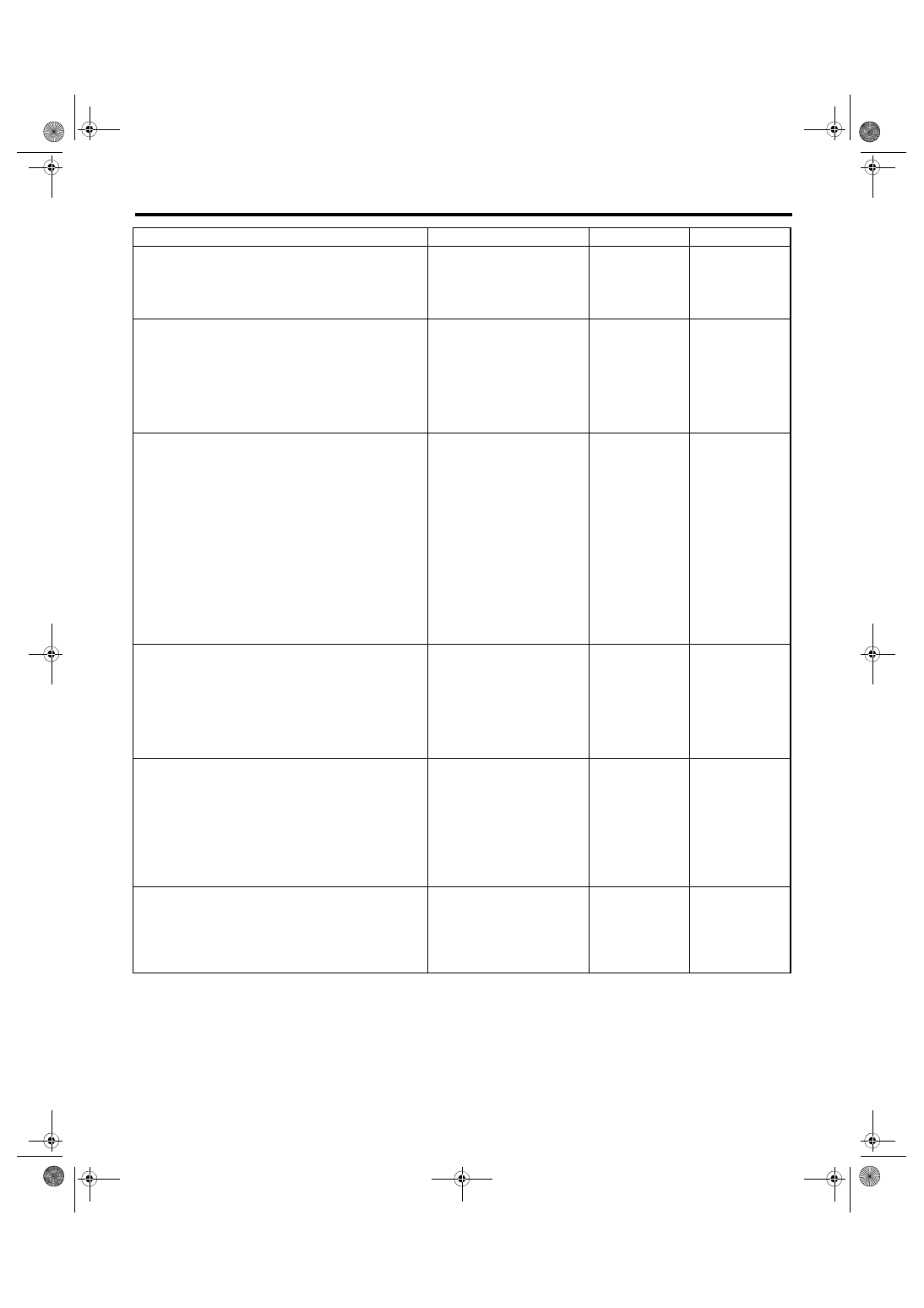
11
CHECK FUSE.
Remove fuse No. 25 from the fuse & relay box,
and perform visual inspection.
Is the fuse OK?
Replace the fuse. If
the fuse is blown
out again, check
the power supply
circuit.
12
CHECK AIRBAG CONTROL MODULE CON-
NECTOR.
1) Turn the ignition switch to OFF, disconnect
the battery ground cable, and wait for 60 sec-
onds or more.
2) Confirm that the connectors of airbag con-
trol module (AB6, AB17, AB18) are securely
connected.
Is the connector of the airbag
control module securely con-
nected?
Connect the con-
nector of the airbag
control module.
13
CHECK THE HARNESS BETWEEN THE AIR-
BAG CONTROL MODULE AND DATA LINK
CONNECTOR.
1) Disconnect the connectors (AB6, AB17,
AB18) from airbag control module.
2) Connect the connector (1AH) in the test har-
ness AH to the connectors (AB6, AB17, AB18).
3) Connect the connector (2AH) in the test har-
ness AH and the connector (1AG) in the test
harness AG.
4) Measure the resistance between connector
(4AG) in the test harness AG and the data link
connector.
Connector & terminal
(4AG) No. 1 — (B40) No. 7:
Is the resistance less than 10
Ω?
Repair the harness
between the airbag
control module and
the data link con-
nector. Or replace
the airbag main
harness along with
the bulkhead har-
ness.
14
CHECK POWER SUPPLY CIRCUIT.
1) Turn the ignition switch to ON.
2) Measure the voltage between connector
(2AG) in the test harness AG and chassis
ground.
Connector & terminal
(2AG) No. 1 (+) — Chassis ground (–):
Is the voltage 10 V or more?
Repair the harness
between the airbag
control module and
the battery. Or
replace the airbag
main harness
along with the bulk-
head harness.
15
CHECK BETWEEN AIRBAG CONTROL
MODULE AND CHASSIS GROUND.
1) Turn the ignition switch to OFF.
2) Measure the resistance between connector
(2AG) in the test harness AG and chassis
ground.
Connector & terminal
(2AG) No. 4 — Chassis ground:
(2AG) No. 3 — Chassis ground:
Is the resistance less than 10
Ω?
Repair the harness
between the airbag
control module and
the chassis
ground. Or replace
the airbag main
harness along with
the bulkhead har-
ness.
16
CHECK POOR CONTACT OF CONNECTOR. Is there poor contact of the con-
trol module power supply,
ground circuit and data link con-
nector?
Repair the connec-
tor. (Replace the
harness instead of
repairing the air-
bag system con-
nector.)
Replace the airbag
control module.
<Ref. to AB-21,
REMOVAL, Airbag
Control Module.>
Step
Check
Yes
No
Нет комментариевНе стесняйтесь поделиться с нами вашим ценным мнением.
Текст