Subaru Impreza 3 / Impreza WRX / Impreza WRX STI. Service manual — part 621
AB(diag)-23
Airbag Connector
AIRBAG SYSTEM (DIAGNOSTICS)
5. Airbag Connector
A: PROCEDURE
For detailed operation procedure, refer to the “Air-
AB(diag)-24
Airbag Control Module I/O Signal
AIRBAG SYSTEM (DIAGNOSTICS)
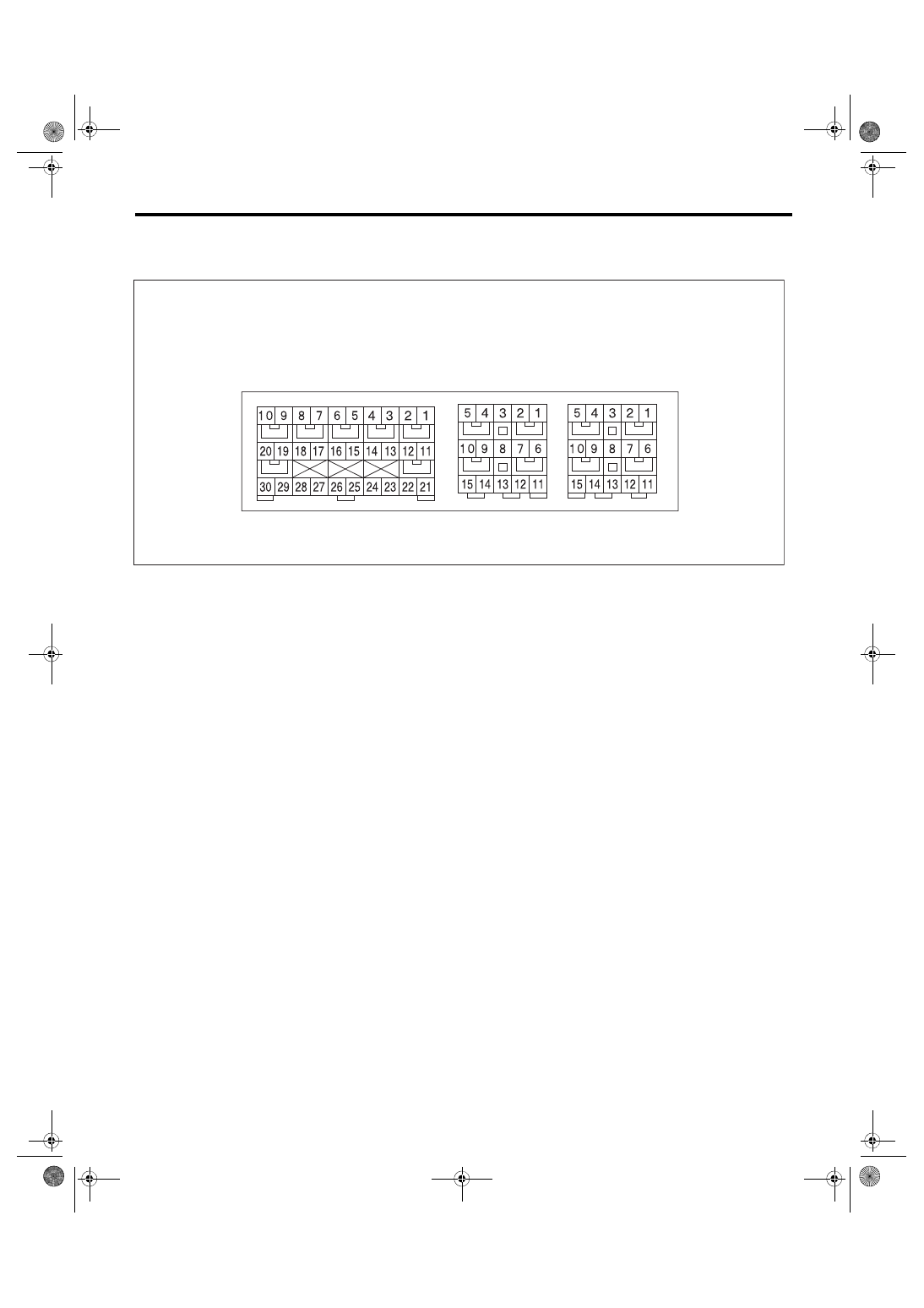
6. Airbag Control Module I/O Signal
A: ELECTRICAL SPECIFICATION
• Terminal numbers in airbag control module connector are shown in the figure.
• The airbag warning light illuminates when the connector is removed from the airbag control module.
AB-02056
(1)
(2)
(3)
AB(diag)-25
Airbag Control Module I/O Signal
AIRBAG SYSTEM (DIAGNOSTICS)
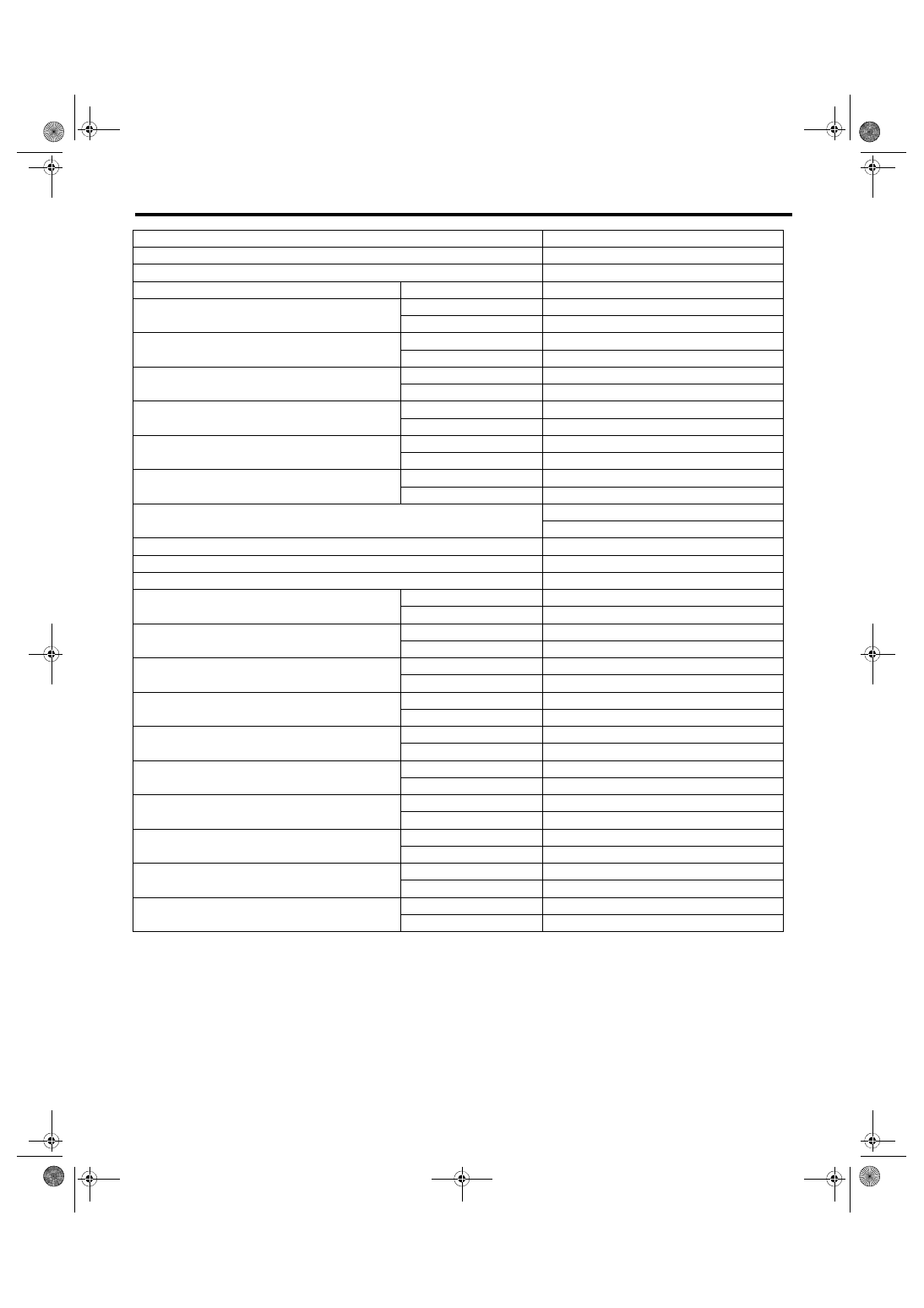
B: WIRING DIAGRAM
Refer to the WI section wiring diagram. <Ref. to WI-82, WIRING DIAGRAM, Airbag System.>
Item
Control module terminal No.
Data link connector
(1) — 16
Combination meter
(1) — 11
Ignition power supply
Dedicated fuse
(1) — 21
Passenger’s airbag module level one
+
(1) — 4
–
(1) — 3
Passenger’s airbag module level two
+
(1) — 1
–
(1) — 2
Driver’s airbag module level one
+
(1) — 5
–
(1) — 6
Driver’s airbag module level two
+
(1) — 8
–
(1) — 7
Front sub sensor LH
+
(1) — 30
–
(1) — 28
Front sub sensor RH
+
(1) — 29
–
(1) — 27
Ground line (GND)
(1) — 25
(1) — 26
Passenger’s airbag OFF indicator
(1) — 17
Passenger’s airbag ON indicator
(1) — 23
Passenger’s seat belt warning light (integrated module)
(1) — 15
Side airbag sensor LH
Curtain airbag sensor LH
+
(2) — 8
–
(2) — 15
Side airbag module LH
+
(2) — 9
–
(2) — 10
Curtain airbag module LH
+
(2) — 7
–
(2) — 6
Seat belt pretensioner LH
+
(2) — 2
–
(2) — 1
Satellite safing sensor
+
(2) — 11
–
(2) — 12
Seat belt pretensioner RH
+
(3) — 4
–
(3) — 5
Side airbag sensor RH
Curtain airbag sensor RH
+
(3) — 8
–
(3) — 11
Side airbag module RH
+
(3) — 7
–
(3) — 6
Curtain airbag module RH
+
(3) — 9
–
(3) — 10
Occupant detection control module
+
(3) — 12
–
(3) — 13
AB(diag)-26
Subaru Select Monitor
AIRBAG SYSTEM (DIAGNOSTICS)
7. Subaru Select Monitor
A: OPERATION
1. READ DIAGNOSTIC TROUBLE CODE
(DTC)
When malfunction of airbag system occurs, the
DTC stored in airbag control module will be read
out.
1) Prepare the Subaru Select Monitor kit. <Ref. to
AB(diag)-8, SPECIAL TOOL, PREPARATION
2) Connect the diagnosis cable to Subaru Select
Monitor.
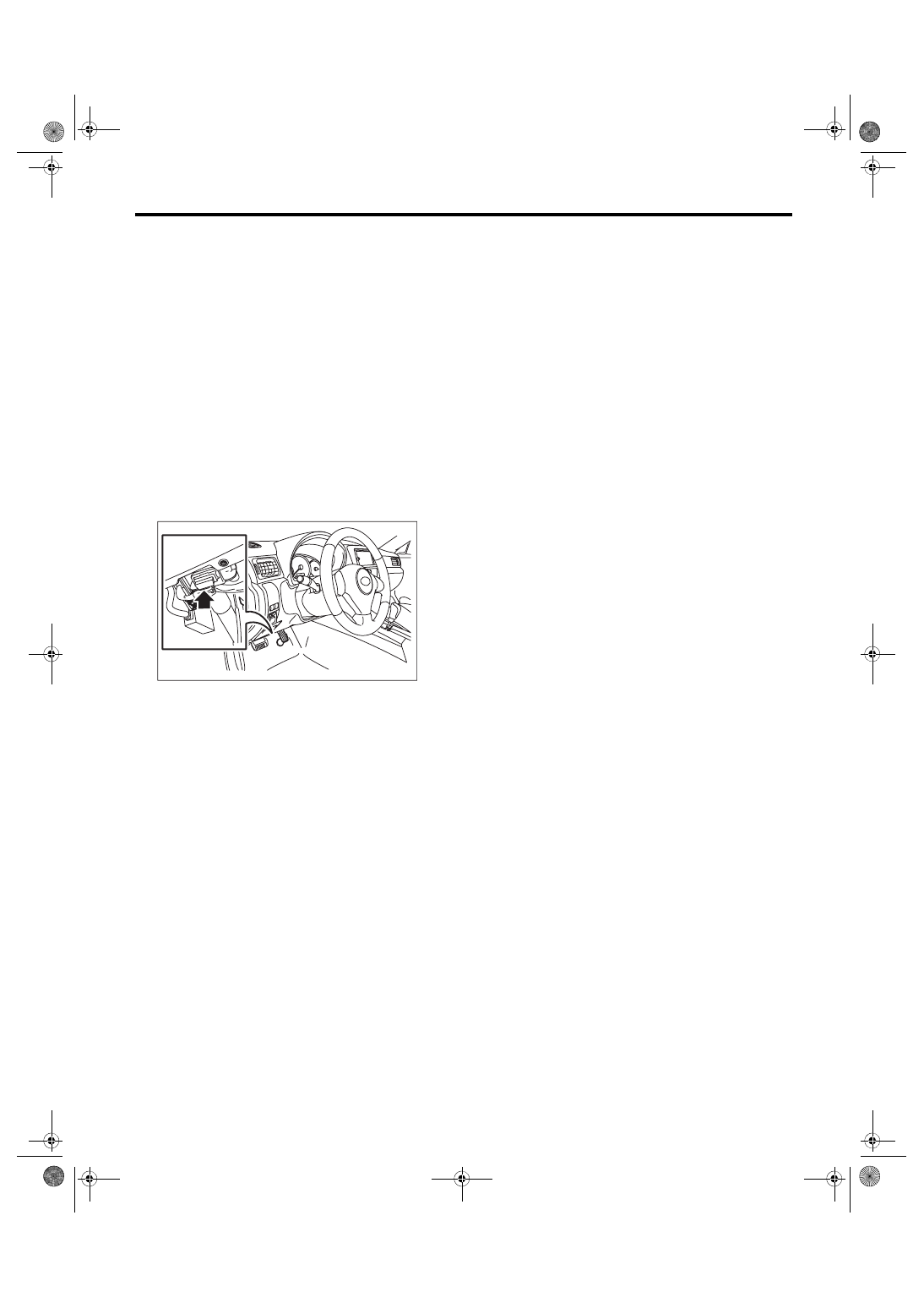
3) Connect the Subaru Select Monitor to data link
connector.
(1) Data link connector is located in the lower
portion of instrument panel (on the driver’s
side).
(2) Connect the diagnosis cable to data link
connector.
CAUTION:
Do not connect the scan tools other than the
Subaru Select Monitor.
4) Turn the ignition switch to ON and run the Suba-
ru Select Monitor.
5) On «Main Menu» display, select {Each System
Check}.
6) On «System Selection Menu» display, select
{Airbag System}.
7) After {Airbag System} is displayed, select [OK].
8) Select the {Diagnostic Code(s) Display} in «Air-
bag System».
NOTE:
• For details concerning the operation procedure,
refer to “PC application help for Subaru Select
Monitor”.
• For details concerning DTCs, refer to List of Di-
agnostic Trouble Code (DTC). <Ref. to AB(diag)-
39, List of Diagnostic Trouble Code (DTC).>
2. CLEAR MEMORY MODE
Clear the DTC stored in the airbag control module
after repairing the airbag system. (After the break-
down is recovered, the breakdown code for com-
pleted recoveries are read out when the next
breakdown occurs if the memory clear work is not
performed.)
1) On «Main Menu» display, select {Each System
Check}.
2) On «System Selection Menu» display, select
{Airbag System}.
3) Select the {Clear Memory} in «Airbag System».
4) When the “Clear Memory?” is shown on the
screen, select [OK].
5) When “Done” is displayed, end the Subaru Se-
lect Monitor.
NOTE:
For detailed operation procedures, refer to “PC ap-
plication help for Subaru Select Monitor”.
IM-00275
Нет комментариевНе стесняйтесь поделиться с нами вашим ценным мнением.
Текст