Subaru Impreza 3 / Impreza WRX / Impreza WRX STI. Service manual — part 93
CO(STI)-4
General Description
COOLING
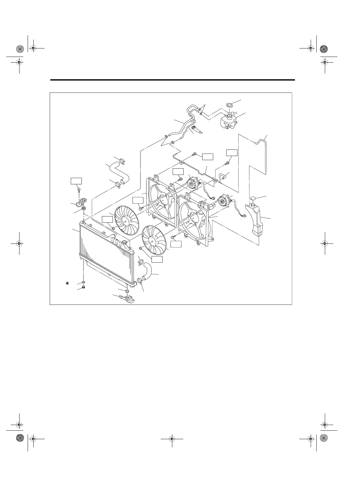
2. RADIATOR AND RADIATOR FAN
(19)
(18)
(21)
(20)
CO-03315
(14)
T1
T3
T3
(9)
(7)
(10)
(8)
(23)
(25)
(24)
(12)
(11)
T2
T2
(5)
(6)
(5)
T3
(1)
(22)
(15)
(5)
(5)
(13)
T1
(2)
(16)
(17)
(3)
(4)
T4
(26)
(26)
CO(STI)-5
General Description
COOLING
C: CAUTION
• Prior to starting work, pay special attention to the following:
1. Always wear work clothes, a work cap, and protective shoes. Additionally, wear a helmet, protective
goggles, etc. if necessary.
2. Protect the vehicle using a seat cover, fender cover, etc.
3. Prepare the service tools, clean cloth, containers to catch grease and oil, etc.
• Prepare a container and cloth to prevent scattering of engine coolant when performing work where engine
coolant can be spilled. If the oil spills, wipe it off immediately to prevent from penetrating into floor or flowing
out for environmental protection.
• Vehicle components are extremely hot immediately after driving. Be wary of receiving burns from heated
parts.
• When performing a repair, identify the cause of trouble and avoid unnecessary removal, disassembly and
replacement.
• Before disconnecting connectors of sensors or units, be sure to disconnect the ground cable from battery.
• Always use the jack-up point when the shop jacks or rigid racks are used to support the vehicle.
• Remove contamination including dirt and corrosion before removal, installation, disassembly or assembly.
• Keep the removed parts in order and protect them from dust and dirt.
• All removed parts, if to be reused, should be reinstalled in the original positions with attention to the correct
directions, etc.
• Bolts, nuts and washers should be replaced with new parts as required.
• Be sure to tighten the fasteners including bolts and nuts to the specified torque.
• Follow all government and local regulations concerning disposal of refuse when disposing engine coolant.
(1)
Radiator lower cushion
(12) Radiator main fan shroud
(23) Over flow hose B
(2)
Radiator
(13) Radiator sub fan
(24) Main fan motor
(3)
Radiator upper cushion
(14) Radiator main fan
(25) Sub fan motor
(4)
Radiator upper bracket
(15) Radiator outlet hose
(26) Clip
(5)
Clip
(16) Radiator drain plug
(6)
Radiator inlet hose
(17) O-ring
Tightening torque: N·m (kgf-m, ft-lb)
(7)
Engine coolant reservoir tank cap
(18) Engine coolant filler tank
T1: 3.4 (0.3, 2.5)
(8)
Over flow hose A
(19) Radiator cap (coolant filler tank
cap)
T2: 4.41 (0.45, 3.25)
(9)
Engine coolant reservoir tank
(20) Engine coolant hose A
T3: 7.5 (0.8, 5.5)
(10) Over flow pipe
(21) Engine coolant hose B
T4: 12 (1.2, 8.9)
(11) Radiator sub fan shroud
(22) Radiator lower bracket
CO(STI)-6
General Description
COOLING
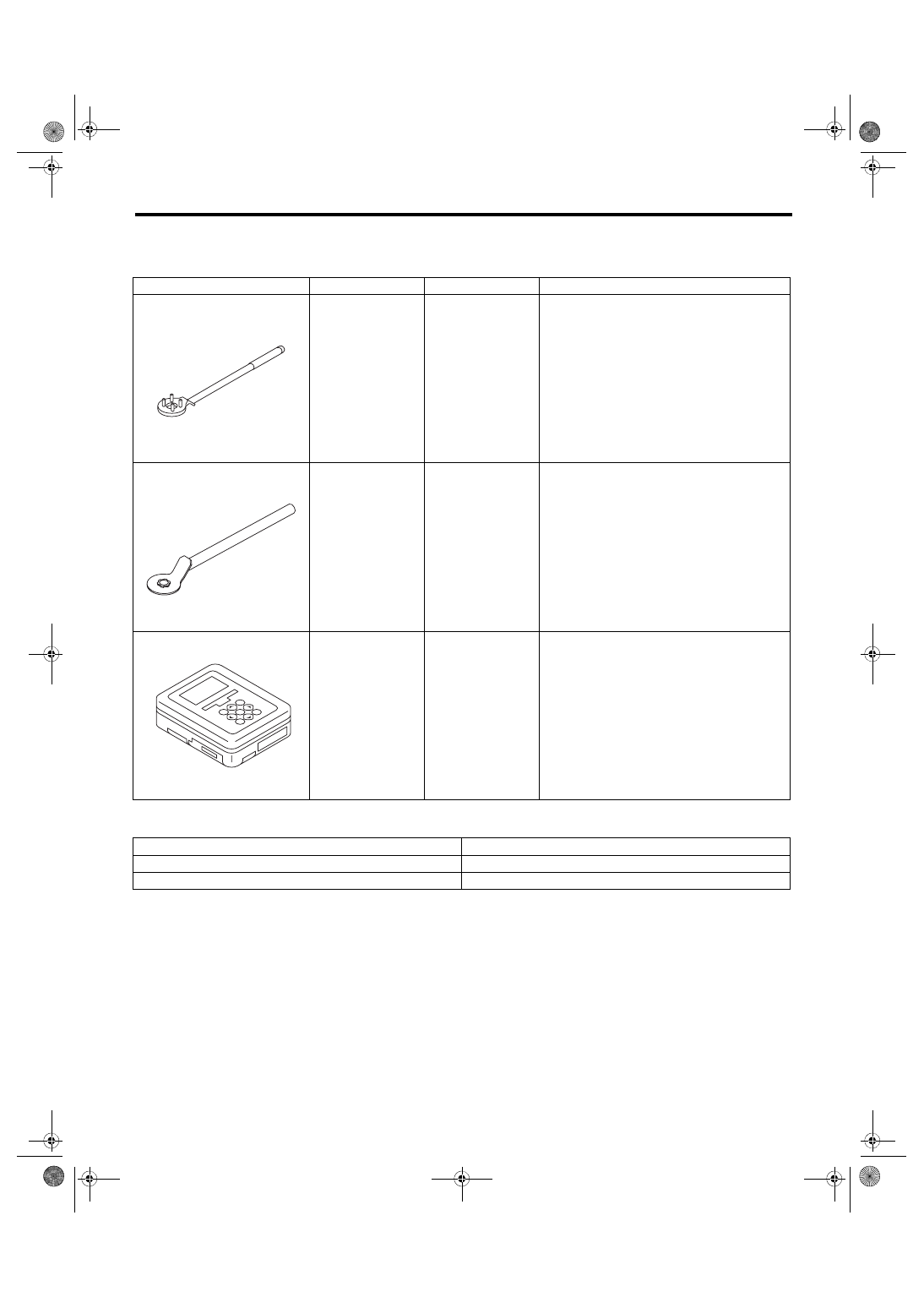
D: PREPARATION TOOL
1. SPECIAL TOOL
2. GENERAL TOOL
ILLUSTRATION
TOOL NUMBER
DESCRIPTION
REMARKS
499977100
CRANK PULLEY
WRENCH
Used for removing and installing the crank pul-
ley.
499977500
CAM SPROCKET
WRENCH
Used for removing and installing intake cam
sprocket and exhaust cam sprocket.
1B022XU0
SUBARU SELECT
MONITOR III KIT
Used for troubleshooting the electrical system.
TOOL NAME
REMARKS
Circuit tester
Used for measuring resistance and voltage.
Radiator cap tester
Used for checking radiator and radiator cap.
ST-499977100
ST-499977500
ST1B022XU0
CO(STI)-7
Radiator Fan System
COOLING
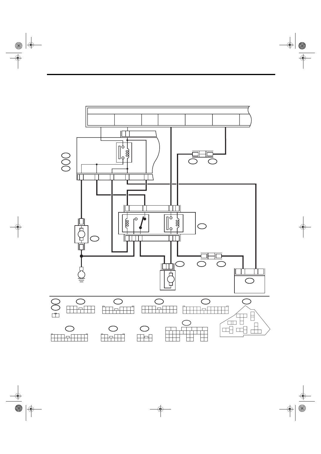
2. Radiator Fan System
A: WIRING DIAGRAM
Radiator Fan System <Ref. to WI-64, WIRING DIAGRAM, Radiator Fan System.>
ECM
19
18
21
20
23
22
24 25
26
17
1
2
3
4
5
6
7
27
28 29 30 31
32 33
34 35
9
8
15
14
13
12
11
10
16
B135
B19
C11
CO-02773
20 21 22
19
18
3 4 5
7
6
10 11
12
13
15
16
17
14
2
1
9
8
E:
C:
B:
12
11
F36
E:
F35
C:
B143
B:
1
10
B360
F109
21
13
10
21
20
B7
C10
E5
E6
12
11
1
8
19
22
1
2
7
16
3
1 2
7
4 5 6
1 2
3 4 5
6 7 8 9 10 11 12
1 2 3 4
5 6 7 8 9
10 11 12 13 14 15 16 17 18 19 20
F27
3 4
1 2
8 9 10 11
12 13 14 15 16 17 18 19 20 21 22 23 24
5
6 7
F109
2 3
4 5 6
8 9 10 11 12 13 14
7
1
B361
F17
B143
F35
F36
F27
2 3
8
10
1
9
4
11 12 13 14 15 16
5 6 7
17 18
F108
1 2 3
4 5 6 7
8 9 10 11 12 13 14 15 16
B360
1 2
F16
F17
B361
F16
F108
B135
E
M
M
THROUGH JOINT
CONNECTOR
SUB FAN MOTOR
MAIN F
AN
MO
TOR
RELAY HOLDER
SUB FAN RELA
Y
MAIN FAN RELA
Y 2
THROUGH JOINT
CONNECTOR
MAIN FAN RELA
Y 1
TO POWER SUPPLY CIRCUIT
F/B FUSE NO. 26
(IG)
M/B FUSE NO. 2
(B)
MB-4
M/B FUSE NO. 3
(B)
FB-46
M/B FUSE NO. 22
(IG)
MAIN FUSE
BOX (M/B)
Нет комментариевНе стесняйтесь поделиться с нами вашим ценным мнением.
Текст