Subaru Impreza 3 / Impreza WRX / Impreza WRX STI. Service manual — part 166
ME(w/o STI)-45
Crank Pulley
MECHANICAL
13.Crank Pulley
A: REMOVAL
NOTE:
When replacing a single part, perform the work with
the engine assembly installed to body.
1) Remove the V-belts. <Ref. to ME(w/o STI)-38,
2) Use the ST to lock the crank pulley, and remove
the crank pulley bolt.
ST 499977100
CRANK PULLEY WRENCH
3) Remove the crank pulley.
B: INSTALLATION
1. METHOD WITHOUT ANGLE GAUGE
1) Clean the crankshaft thread using compressed
air.
2) Install the crank pulley.
3) Apply engine oil to the crank pulley bolt seat and
thread.
4) Tighten the crank pulley bolts.
(1) Use the ST to lock the crank pulley, and
temporarily tighten the crank pulley bolt.
ST 499977100
CRANK PULLEY WRENCH
Tightening torque:
47 N·m (4.8 kgf-m, 34.7 ft-lb)
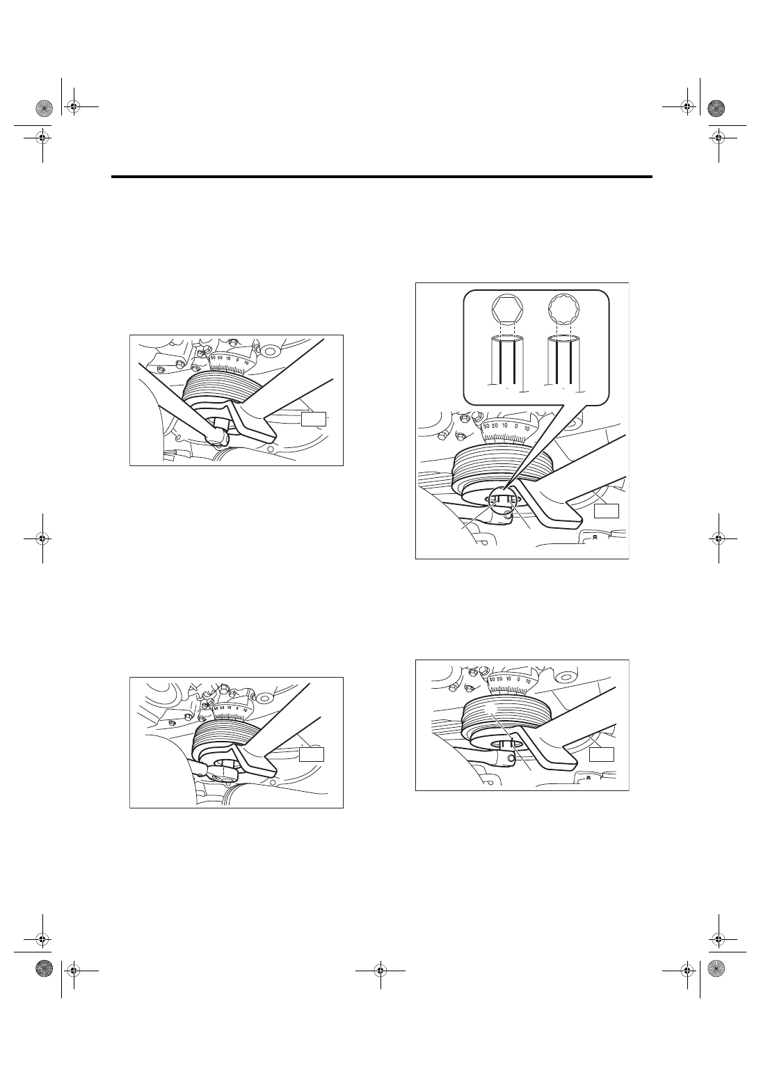
(2) Draw reference lines (A) and (B) using a
marker to set the socket to the crank pulley bolt
as shown in the figure.
NOTE:
Set the socket onto the crank pulley bolt so that ref-
erence lines (A) and (B) is visible.
ST 499977100
CRANK PULLEY WRENCH
(3) Draw end line (C) on ST using a marker at
the same position as reference line (B) drawn
on the socket in step (2).
ST 499977100
CRANK PULLEY WRENCH
ME-04141
ST
ST
ME-04142
(a) When using 6-point socket
(b) When using 12-point socket
ME-04955
(B)
ST
(A)
(a)
(B)
(A)
(b)
(B)
(A)
ME-04144
(B)
ST
(C)
ME(w/o STI)-46
Crank Pulley
MECHANICAL
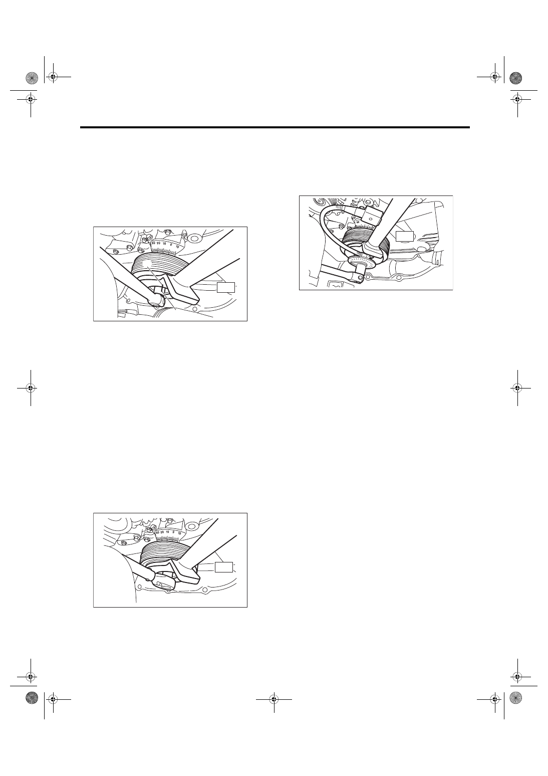
(4) Use the ST to lock the crank pulley, and
tighten the crank pulley bolt to the angle where
reference line (A) and end line (C) are aligned.
NOTE:
It should be approx. 60° when reference line (A)
and end line (C) are aligned.
ST 499977100
CRANK PULLEY WRENCH
Tightening angle:
60°
±
5°
5) Install the V-belts. <Ref. to ME(w/o STI)-38, IN-
2. METHOD WITH ANGLE GAUGE
1) Clean the crankshaft thread using compressed
air.
2) Install the crank pulley.
3) Apply engine oil to the crank pulley bolt seat and
thread.
4) Tighten the crank pulley bolts.
(1) Remove the radiator main fan motor assem-
bly and radiator sub fan motor assembly. <Ref.
to CO(w/o STI)-23, REMOVAL, Radiator Main
Fan and Fan Motor.> <Ref. to CO(w/o STI)-25,
REMOVAL, Radiator Sub Fan and Fan Motor.>
(2) Use the ST to lock the crank pulley, and
temporarily tighten the crank pulley bolt.
ST 499977100
CRANK PULLEY WRENCH
Tightening torque:
47 N·m (4.8 kgf-m, 34.7 ft-lb)
(3) Set the angle gauge, use the ST to lock the
crank pulley, and tighten the crank pulley bolt to
the specified angle.
ST 499977100
CRANK PULLEY WRENCH
Tightening angle:
60°
±
5°
(4) Install the radiator main fan motor assembly
and radiator sub fan motor assembly. <Ref. to
CO(w/o STI)-23, INSTALLATION, Radiator
Main Fan and Fan Motor.> <Ref. to CO(w/o
STI)-25, INSTALLATION, Radiator Sub Fan
5) Install the V-belts. <Ref. to ME(w/o STI)-38, IN-
C: INSPECTION
1) Check that the crank pulley has no deformation,
cracks or other damages.
ME-04145
ST
(A)
(C)
ME-07558
ST
ME-07555
ST
ME(w/o STI)-47
Timing Belt Cover
MECHANICAL
14.Timing Belt Cover
A: REMOVAL
NOTE:
When replacing a single part, perform the work with
the engine assembly installed to body.
1) Remove the secondary air pump. <Ref. to EC(w/
o STI)-29, REMOVAL, Secondary Air Pump.>
2) Remove the crank pulley. <Ref. to ME(w/o STI)-
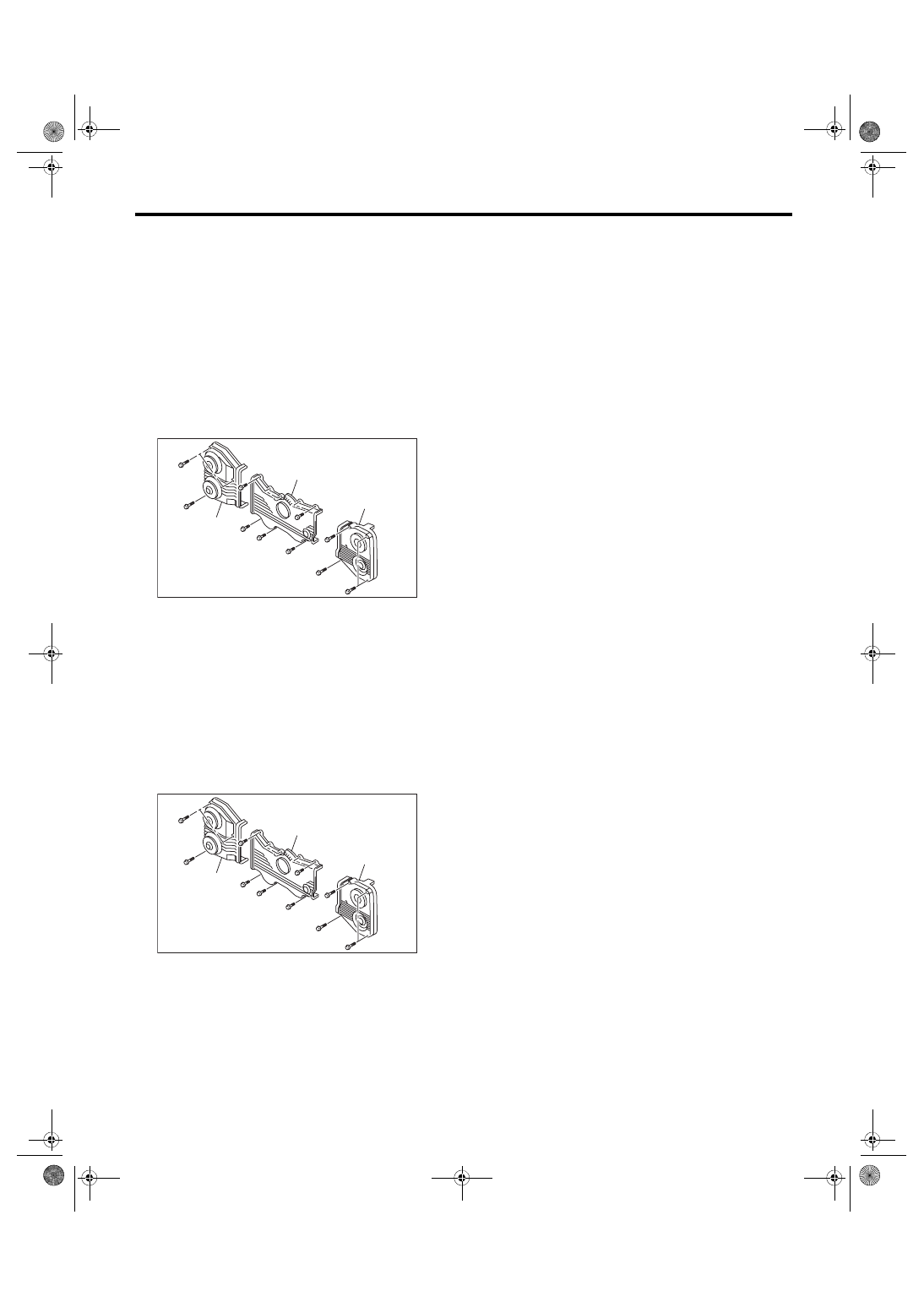
3) Remove the timing belt cover RH (A).
4) Remove the timing belt cover LH (B).
5) Remove the front timing belt cover (C).
B: INSTALLATION
1) Install the front timing belt cover (C).
Tightening torque:
5 N·m (0.5 kgf-m, 3.7 ft-lb)
2) Install the timing belt cover LH (B).
Tightening torque:
5 N·m (0.5 kgf-m, 3.7 ft-lb)
3) Install the timing belt cover RH (A).
Tightening torque:
5 N·m (0.5 kgf-m, 3.7 ft-lb)
4) Install the crank pulley. <Ref. to ME(w/o STI)-45,
5) Install the secondary air pump. <Ref. to EC(w/o
STI)-29, INSTALLATION, Secondary Air Pump.>
C: INSPECTION
Check the timing belt cover for damage.
ME-04754
(A)
(C)
(B)
ME-04754
(A)
(C)
(B)
ME(w/o STI)-48
Timing Belt
MECHANICAL
15.Timing Belt
A: REMOVAL
NOTE:
• When replacing a single part, perform the work
with the engine assembly installed to body.
• When performing the work with the engine in-
stalled to body, the following parts must also be re-
moved/installed.
• Radiator main fan motor assembly <Ref. to
CO(w/o STI)-23, REMOVAL, Radiator Main Fan
and Fan Motor.> <Ref. to CO(w/o STI)-23, IN-
STALLATION, Radiator Main Fan and Fan Mo-
• Radiator sub fan motor assembly <Ref. to
CO(w/o STI)-25, REMOVAL, Radiator Sub Fan
and Fan Motor.> <Ref. to CO(w/o STI)-25, IN-
STALLATION, Radiator Sub Fan and Fan Mo-
• When performing the work with the engine in-
stalled to body, protect the radiator with cardboards
or blankets.
1. TIMING BELT
1) Remove the crank pulley. <Ref. to ME(w/o STI)-
2) Remove the timing belt cover. <Ref. to ME(w/o
STI)-47, REMOVAL, Timing Belt Cover.>
3) Remove the timing belt guide.
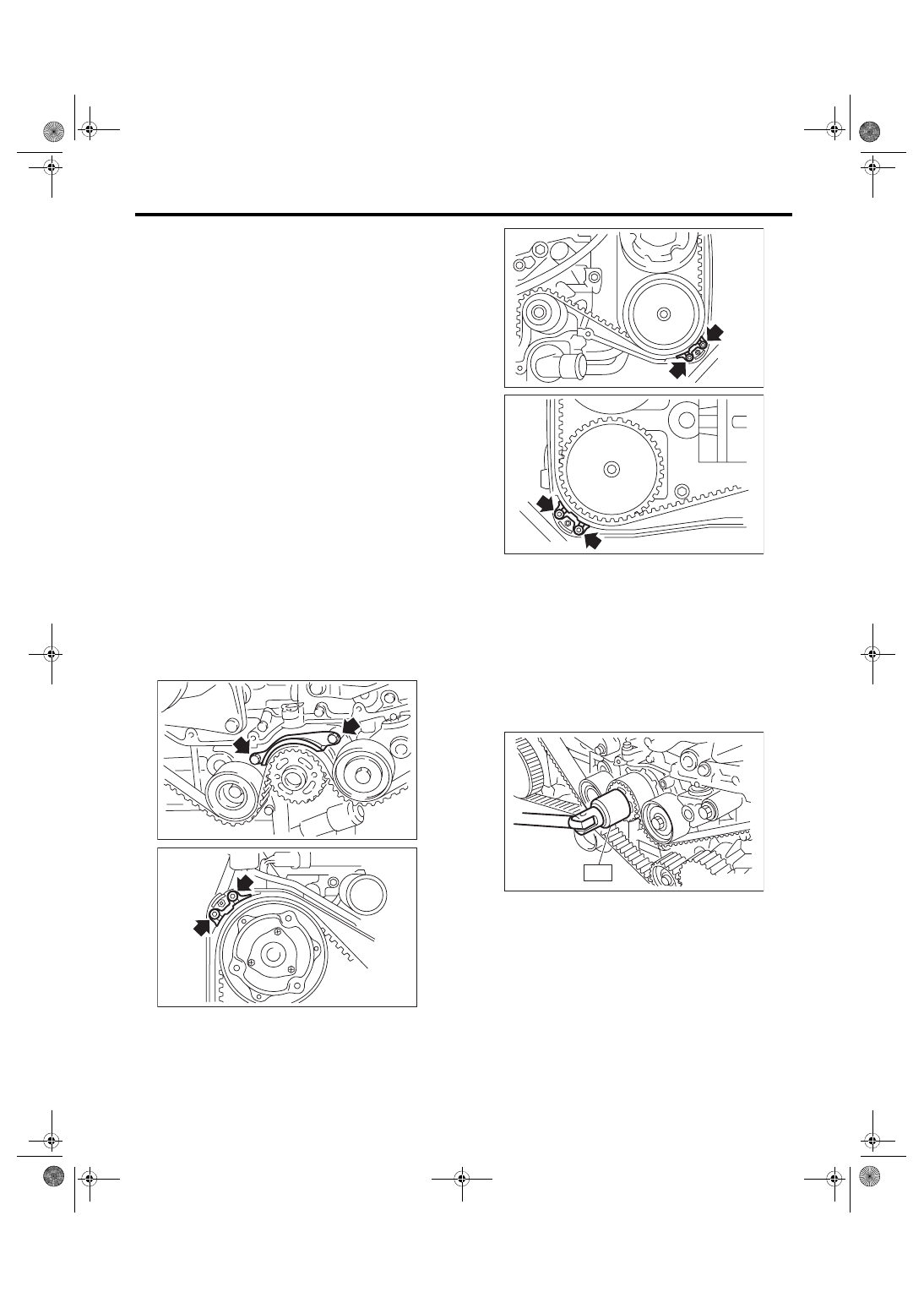
4) If the alignment mark or arrow mark (which indi-
cates the direction of rotation) on timing belt fade
away, put new marks before removing the timing
belt as shown in procedures below.
(1) Turn the crankshaft using ST, and align the
alignment marks on crank sprocket, intake cam
sprocket LH, exhaust cam sprocket LH, intake
cam sprocket RH and exhaust cam sprocket
RH with marks on oil pump and notches of tim-
ing belt cover.
ST 499987500
CRANKSHAFT SOCKET
ME-00230
ME-03124
ME-00728
ME-00729
ME-00231
ST
Нет комментариевНе стесняйтесь поделиться с нами вашим ценным мнением.
Текст