Subaru Impreza 3 / Impreza WRX / Impreza WRX STI. Service manual — part 167
ME(w/o STI)-49
Timing Belt
MECHANICAL
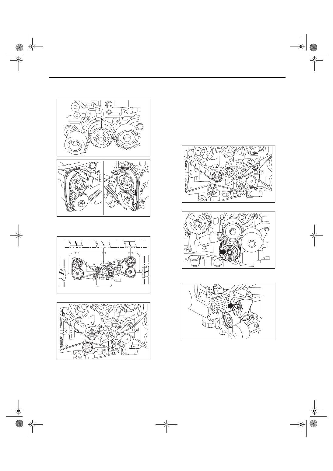
(2) Using white paint, put an alignment mark or
an arrow mark on timing belts in relation to the
crank sprocket and cam sprockets.
Z
1
: 54.5 teeth
Z
2
: 51 teeth
Z
3
: 28 teeth
5) Remove the belt idler (A).
6) Remove the timing belt.
CAUTION:
After the timing belt has been removed, never
rotate the intake and exhaust sprocket. If the
cam sprocket is rotated, the intake and exhaust
valve heads strike together and valve stems are
bent.
2. AUTOMATIC BELT TENSION ADJUST-
ER ASSEMBLY AND BELT IDLER
1) Remove the belt idler (A) and (B).
2) Remove the belt idler No. 2.
3) Remove the automatic belt tension adjuster as-
sembly.
ME-00070
ME-03175
ME-03176
Z
3
Z
1
Z
2
Z
3
(A)
ME-03935
(A)
(B)
ME-03936
ME-04977
ME-04978
ME(w/o STI)-50
Timing Belt
MECHANICAL
B: INSTALLATION
1. AUTOMATIC BELT TENSION ADJUST-
ER ASSEMBLY AND BELT IDLER
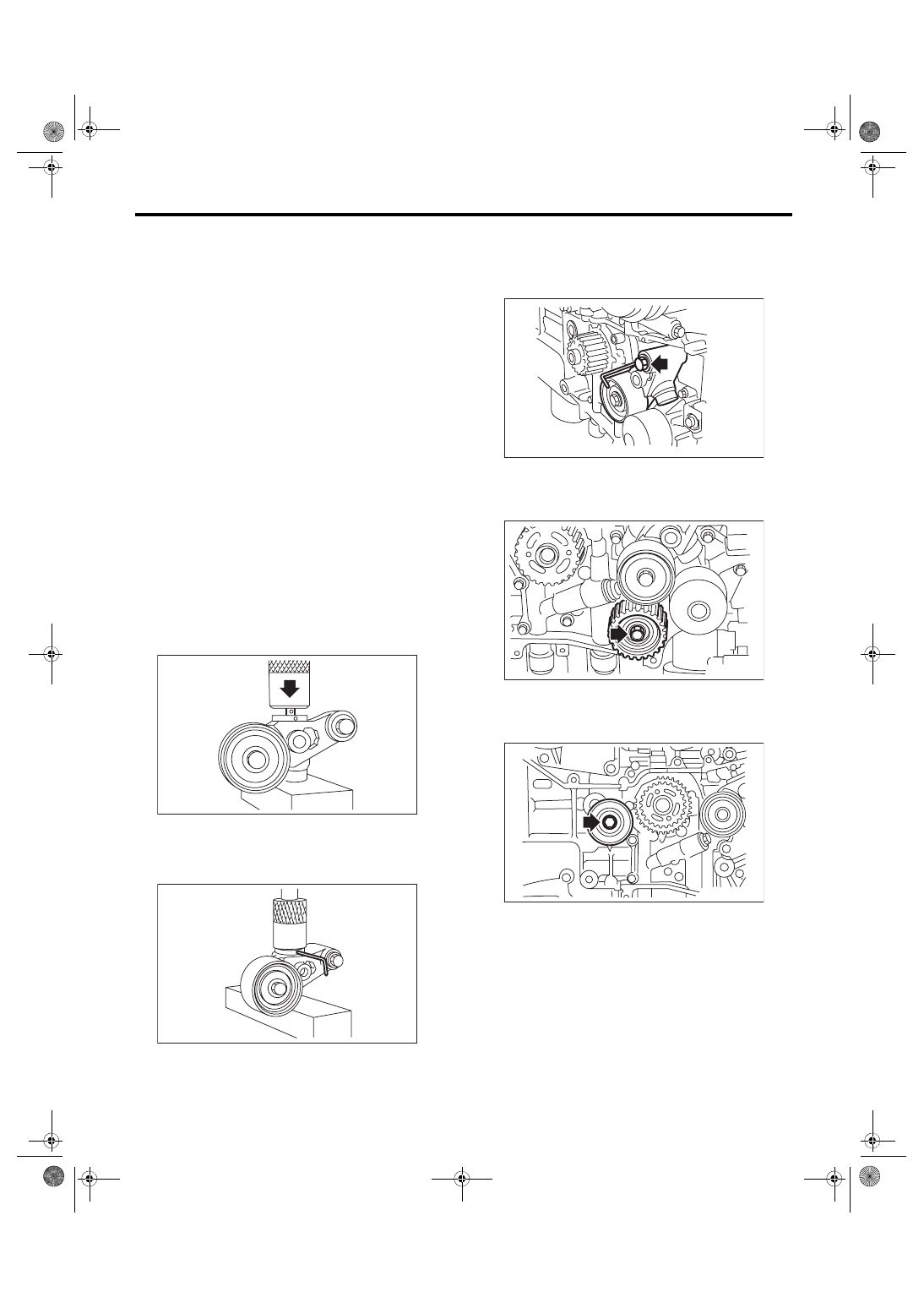
1) Prepare for installation of the automatic belt ten-
sion adjuster assembly.
CAUTION:
• Always use a vertical type pressing tool to
move the adjuster rod down.
• Do not use a lateral type vise.
• Push the adjuster rod vertically.
• Press-in the push adjuster rod gradually tak-
ing three minutes or more.
• Do not allow press pressure to exceed 9,807
N (1,000 kgf, 2,205 lb).
• Push in the adjuster rod to the end face of the
cylinder. However, do not press the adjuster
rod below the end face of the cylinder. Doing so
may damage the cylinder.
• Do not release the press pressure until stop-
per pin is completely inserted.
(1) Attach the automatic belt tension adjuster
assembly to vertical pressing tool.
(2) Slowly push in the adjuster rod with a pres-
sure of 165 N (16.8 kgf, 37.1 lbf) or more until
the adjuster rod is aligned with the stopper pin
hole in the cylinder.
(3) With a 2 mm (0.08 in) dia. stopper pin or a 2
mm (nominal) dia. hex wrench inserted into the
stopper pin hole in cylinder, secure the adjuster
rod.
2) Install the automatic belt tension adjuster as-
sembly.
Tightening torque:
39 N·m (4.0 kgf-m, 28.8 ft-lb)
3) Install the belt idler No. 2.
Tightening torque:
39 N·m (4.0 kgf-m, 28.8 ft-lb)
4) Install the belt idlers.
Tightening torque:
39 N·m (4.0 kgf-m, 28.8 ft-lb)
ME-00239
ME-00350
ME-04979
ME-04977
ME-04980
ME(w/o STI)-51
Timing Belt
MECHANICAL
Tightening torque:
25 N·m (2.5 kgf-m, 18.4 ft-lb)
2. TIMING BELT
1) Prepare for installation of the automatic belt ten-
sion adjuster assembly. <Ref. to ME(w/o STI)-50,
AUTOMATIC BELT TENSION ADJUSTER AS-
SEMBLY AND BELT IDLER, INSTALLATION,
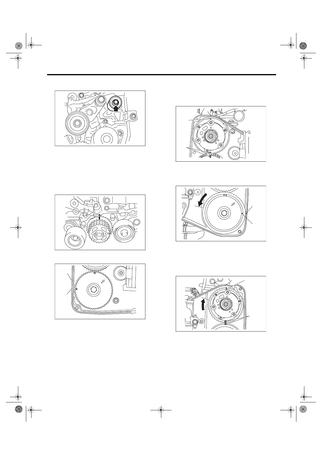
2) Align the mark (B) on crank sprocket with the
mark (A) on oil pump.
3) Align the single line mark (B) on the exhaust cam
sprocket RH with notch (A) on the timing belt cover.
4) Align the single line mark (B) on the intake cam
sprocket RH with notch (A) on the timing belt cover.
Make sure that the double line marks (C) on intake
cam sprocket and exhaust cam sprocket are
aligned.
5) Align the single line mark (B) on exhaust cam
sprocket LH with notch (A) on the timing belt cover
by turning the sprocket counterclockwise (as
viewed from front of engine).
6) Align the single line mark (B) on intake cam
sprocket LH with notch (A) on the timing belt cover
by turning the sprocket clockwise (as viewed from
front of engine). Make sure that the double line
marks (C) on intake cam sprocket and exhaust cam
sprocket are aligned.
ME-04981
(B)
ME-04082
(A)
ME-04088
(A)
(B)
ME-04084
(A)
(C)
(B)
ME-04089
(B)
(A)
ME-04086
(B)
(A)
(C)
ME(w/o STI)-52
Timing Belt
MECHANICAL
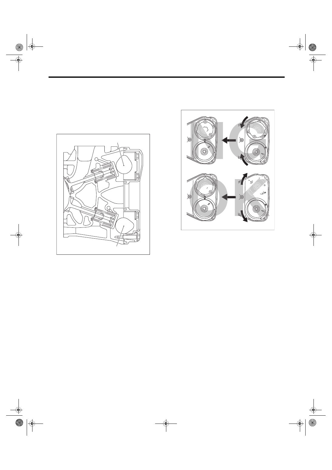
7) Make sure that the cam and crank sprockets are
positioned properly.
CAUTION:
• Intake and exhaust camshafts for this DOHC
engine can be independently rotated with the
timing belts removed. As can be seen from the
figure, if the intake and exhaust valves are lifted
simultaneously, heads will interfere with each
other, resulting in bent valves.
• When the timing belts are not installed, four
camshafts are held at the “zero-lift” position,
where all cams on camshafts are not pushing
down on the intake and exhaust valves. (Under
this condition, all valves remain unlifted.)
• When the camshafts are rotated to install the
timing belts, #2 intake and #4 exhaust cam of
camshaft LH are held, pushing their corre-
sponding valves down. (Under this condition,
these valves are held lifted.) Camshaft RH are
held so that their cams do not push the valves
down.
• Camshafts LH must be rotated from the zero-
lift position to the position where the timing belt
is to be installed with the smallest possible an-
gle, in order to prevent mutual interference of
intake and exhaust valve heads.
• Do not allow the camshafts to rotate in the di-
rection shown in the upper figure. Doing this
may cause both the intake and exhaust valves
to lift simultaneously, resulting in mutual inter-
ference of valve heads.
(A) Intake camshaft
(B) Exhaust camshaft
ME-04111
(A)
(B)
(A) Direction of rotation
(B) Timing belt installation position
(A)
(A)
(A)
(A)
(B)
(B)
ME-04680
Нет комментариевНе стесняйтесь поделиться с нами вашим ценным мнением.
Текст