Subaru Impreza 3 / Impreza WRX / Impreza WRX STI. Service manual — part 472
FS-23
Front Arm
FRONT SUSPENSION
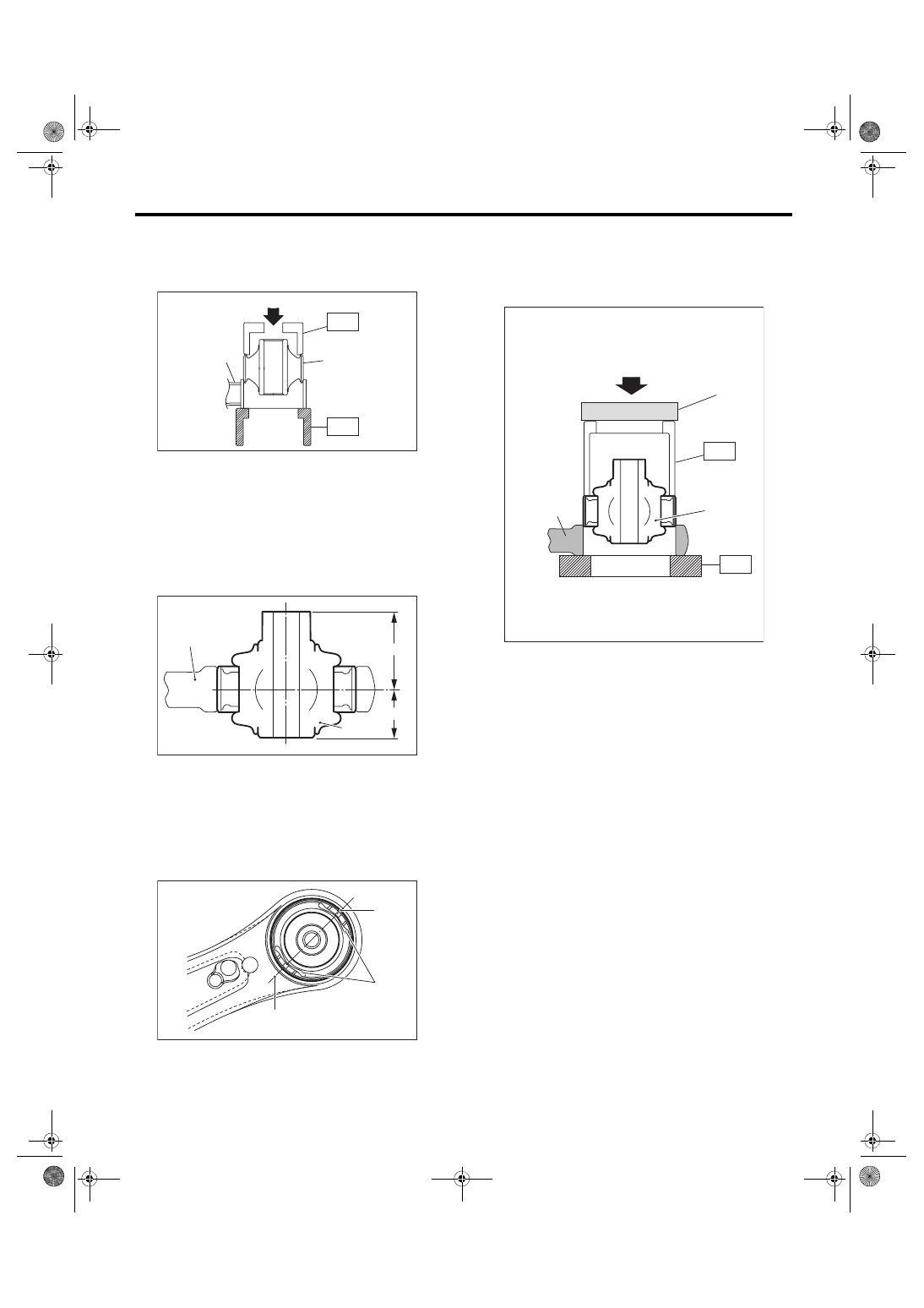
3) Using the ST and a press, install the rear bush-
ing.
ST1 20299AG000 REMOVER
ST2 20299AG010 BASE
Aluminum front arm
1) Install the pillow ball bushing with its longer inner
cylinder facing upward and the shorter facing
downward as shown in the figure.
2) Align the center of rear bushing recess portion
with the aligning mark on the front arm.
3) Using the ST and a press, install the rear bush-
ing.
ST1 20299AE020
INSTALLER & REMOVER
ST2 18723AA000
REMOVER ASSY (GEAR
DRIVEN)
NOTE:
Place the plate on the ST1 to use the press.
E: INSPECTION
1) Check the front arm for damage or cracks, and
correct or replace if defective.
2) Check the bushing for abnormal fatigue or dam-
age.
3) Check the pillow ball bushing for damage or
cracks, and replace if defective.
4) Try to wobble the pillow ball bushing. Replace
the pillow ball bushing if backlash or resistance are
found.
(1) Press
(2) Front arm
(3) Rear bushing
(1) Front arm
(2) Bushing inner cylinder
(3) Longer
(4) Shorter
(1) Alignment mark
(2) Recess section
FS-00127
(1)
(2)
(3)
ST2
ST1
FS-00441
(1)
(2)
(3)
(4)
FS-00440
(1)
(2)
(1)
(1) Press
(2) Front arm
(3) Rear bushing
(4) Plate
FS-00426
(1)
(2)
(3)
ST1
(4)
ST2
FS-24
Front Strut
FRONT SUSPENSION
7. Front Strut
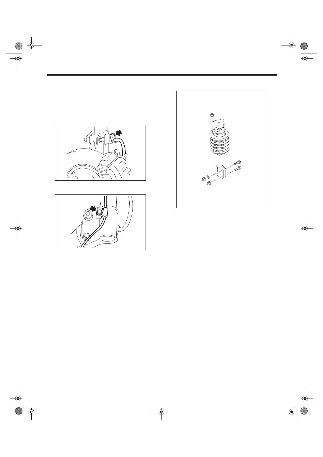
A: REMOVAL
1) Lift up the vehicle, and then remove the front
wheels.
2) Place an alignment mark on the camber adjust-
ing bolt and strut.
3) Remove the brake hose bracket.
4) Remove the bolt securing the ABS wheel speed
sensor harness.
5) Remove the two bolts securing the housing to
the strut.
NOTE:
While holding the head of the adjusting bolt, loosen
the flange nut.
6) Remove the three nuts securing strut mount to
body.
B: INSTALLATION
1) Install the strut mount at the upper side of strut to
body, and tighten it with new self-locking nuts.
Tightening torque:
20 N·m (2.0 kgf-m, 14.8 ft-lb)
2) Align alignment marks on the camber adjusting
bolt and strut.
Using new flange nuts, install the strut to the hous-
ing.
NOTE:
While holding the head of adjusting bolt, tighten the
flange nut.
Tightening torque:
155 N·m (15.8 kgf-m, 114.3 ft-lb)
3) Secure the ABS wheel speed sensor harness to
the strut.
Tightening torque:
33 N·m (3.4 kgf-m, 24.3 ft-lb)
4) Install the brake hose bracket.
Tightening torque:
33 N·m (3.4 kgf-m, 24.3 ft-lb)
5) Install the front wheels.
6) Inspect the wheel alignment and adjust if neces-
sary.
FS-00037
FS-00038
FS-00039
FS-25
Front Strut
FRONT SUSPENSION
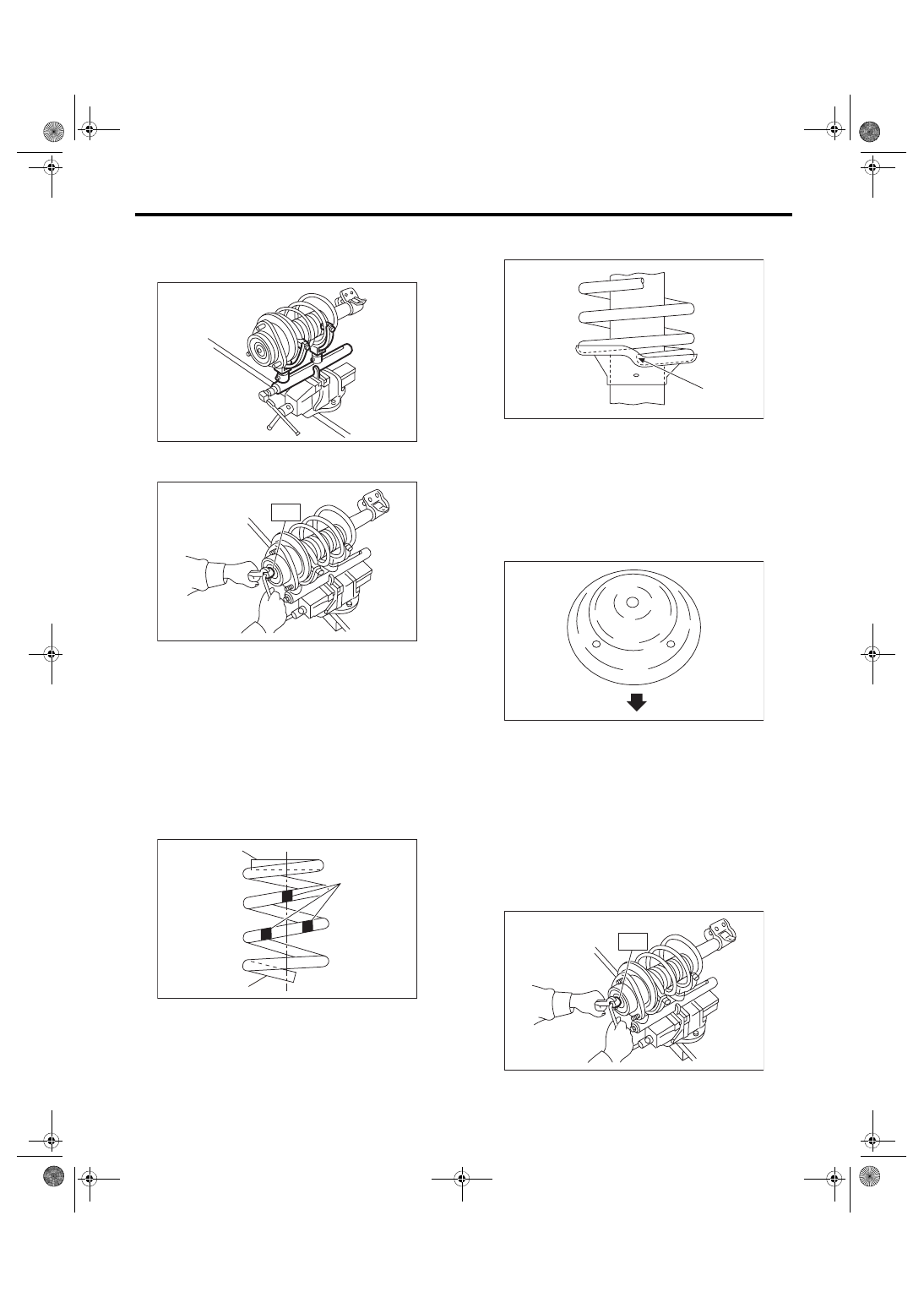
C: DISASSEMBLY
1) Using a coil spring compressor, compress the
coil spring.
2) Using the ST, remove the self-locking nut.
ST 20399AG000 STRUT MOUNT SOCKET
3) Remove the strut mount and upper spring seat
from strut.
4) Gradually decrease the compression force of
compressor, and remove the coil spring.
5) Remove the dust cover.
D: ASSEMBLY
1) Using a coil spring compressor, compress the
coil spring.
NOTE:
Make sure that the vertical install direction of the
coil spring is as shown in the figure.
2) Set the coil spring correctly so that its end face
seats well in the spring seat as shown in the figure.
3) Install the dust cover to the piston rod.
4) Pull the piston rod fully upward, and install the
spring seat.
NOTE:
Position the upper spring seat as shown in the fig-
ure.
5) Install the strut mount and spacer to piston rod,
and temporarily attach and tighten a new self lock-
ing nut.
6) Using a hexagon wrench to prevent strut rod
from turning, tighten the new self-locking nut with
ST.
ST 20399AG000 STRUT MOUNT SOCKET
Tightening torque:
55 N·m (5.6 kgf-m, 40.6 ft-lb)
7) Loosen the coil spring compressor carefully.
(1) Diameter is small (upper part)
(2) Identification paint
(3) Diameter is large (bottom part)
FS-00040
FS-00041
ST
FS-00042
(2)
(1)
(3)
(1) Coil spring end face
(1) Outside of body
FS-00043
(1)
FS-00128
(1)
FS-00041
ST
FS-26
Front Strut
FRONT SUSPENSION
E: INSPECTION
Check the removed part for wear, damage and
cracks, and then repair or replace it if defective.
1. STRUT
1) Check for oil leaks.
2) Move the piston rod up and down to check that it
operates smoothly without any hitch.
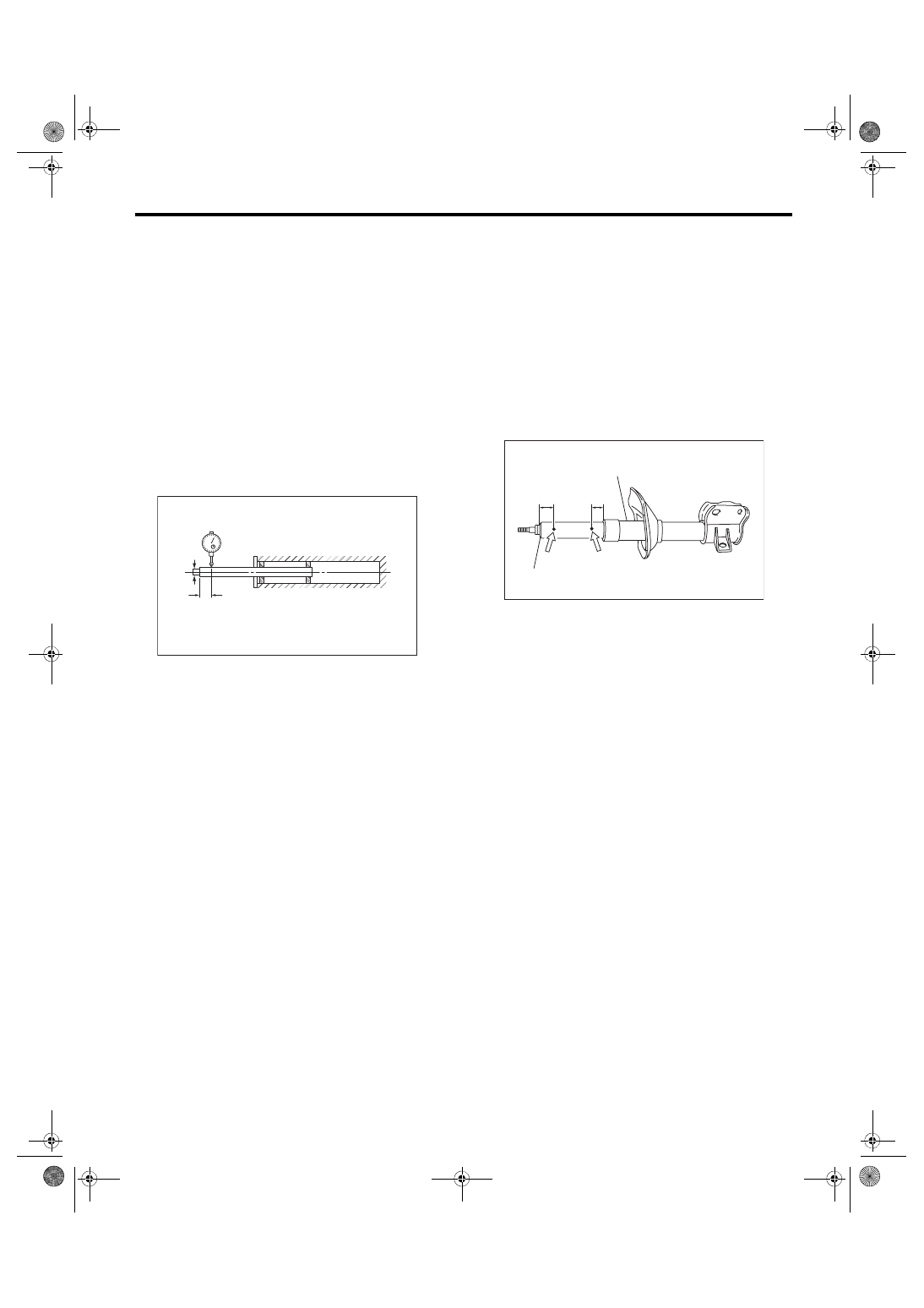
3) Piston rod play
• Measure the play as follows:
Fix the outer shell in place and fully extend the rod.
Set a dial gauge at the end of rod L [10 mm (0.39
in)], and then read the dial gauge indication P
1
while applying a force of W [20 N (2 kgf, 4 lbf)] to
the threaded portion. Apply a force of 20 N (2 kgf, 4
lbf) from the opposite direction of “W”, and then
read the dial gauge indication P
2
.
Play limit (P
1
+ P
2
):
0.8 mm (0.031 in)
If the play exceeds limit, replace the strut.
2. STRUT MOUNT
Check the rubber part for deformation, cracks or
deterioration, and then replace it with a new part if
defective.
3. DUST COVER
If cracks or damage are found, replace with a new
part.
4. COIL SPRING
If a permanent strain is found, replaced it with a
new part.
5. HELPER
If major cracks or damage are found, replace it with
a new part. (Except for STI model)
F: DISPOSAL
CAUTION:
• Before handling struts, be sure to wear gog-
gles to protect eyes from gas, oil and cutting
powder.
• Do not disassemble the strut damper or
throw into flames.
• When discarding gas filled struts, drill holes
in them to purge the gas.
1) Place the strut on a level surface with the piston
rod fully expanded.
2) Using a 2 — 3 mm (0.08 — 0.12 in) dia. drill,
make a hole into the position (1) first, and then (2).
FS-00046
W
L
(1) 20 mm (0.78 in)
(2) 10 mm (0.39 in)
(3) Strut
(4) Damping tube
FS-00096
(1)
(4)
(2)
(3)
Нет комментариевНе стесняйтесь поделиться с нами вашим ценным мнением.
Текст