Subaru Impreza 3 / Impreza WRX / Impreza WRX STI. Service manual — part 213
EN(H4DOTC)(diag)-76
Diagnostics for Engine Starting Failure
ENGINE (DIAGNOSTICS)
3
CHECK DTC.
Is DTC displayed? <Ref. to
EN(H4DOTC)(diag)-48,
OPERATION, Read Diagnostic
Trouble Code (DTC).>
4
CHECK INPUT SIGNAL FOR STARTER MO-
TOR.
1) Turn the ignition switch to OFF.
2) Disconnect the connector from starter
motor.
3) Depress the clutch pedal.
4) Turn the ignition switch to START.
5) Measure the voltage between the starter
motor connector and the engine ground.
Connector & terminal
(B14) No. 1 (+) — Engine ground (–):
Is the voltage 10 V or more?
Check the starter
motor. <Ref. to
SC(STI)-8,
Starter.>
5
CHECK INPUT SIGNAL FOR STARTER MO-
TOR.
1) Depress the clutch pedal.
2) Turn the ignition switch to START.
3) Measure the voltage between starter relay
connector and chassis ground.
Connector & terminal
(B225) No. 10 (+) — Chassis ground (–):
Is the voltage 10 V or more?
Repair the open
circuit of the har-
ness between
starter relay con-
nector and starter
motor.
6
CHECK HARNESS BETWEEN BATTERY
AND IGNITION SWITCH CONNECTOR.
1) Turn the ignition switch to OFF.
2) Disconnect the connector from ignition
switch.
3) Measure the voltage between ignition
switch connector and chassis ground.
Connector & terminal
(B72) No. 3 (+) — Chassis ground (–):
Is the voltage 10 V or more?
Repair the power
supply circuit.
7
CHECK IGNITION SWITCH.
Measure the resistance between ignition switch
terminals after turning the ignition switch to
START position.
Terminals
No. 2 — No. 3:
No. 6 — No. 3:
Is the resistance less than 1 Ω? Go to step
Replace the igni-
tion switch. <Ref.
to SL-42,
REPLACEMENT,
Ignition Key Lock.>
8
CHECK INPUT VOLTAGE OF CLUTCH
START SWITCH.
1) Turn the ignition switch to OFF.
2) Disconnect the clutch start switch connec-
tor.
3) Connect the connector to ignition switch.
4) Turn the ignition switch to START.
5) Measure the voltage between the clutch
start switch connector and chassis ground.
Connector & terminal
(B106) No. 1 (+) — Chassis ground (–):
Is the voltage 10 V or more?
Check the follow-
ing item and repair
if necessary.
• Blown out of fuse
(F/B No. 21)
• Open or short
circuit to ground in
harness between
ignition switch con-
nector and clutch
start switch con-
nector
Step
Check
Yes
No
EN(H4DOTC)(diag)-77
Diagnostics for Engine Starting Failure
ENGINE (DIAGNOSTICS)
9
CHECK HARNESS BETWEEN STARTER RE-
LAY CONNECTOR AND CLUTCH START
SWITCH CONNECTOR.
1) Turn the ignition switch to OFF.
2) Remove the starter relay.
3) Measure the resistance of harness between
starter relay connector and clutch start switch
connector.
Connector & terminal
(B225) No. 11 — (B106) No. 2:
Is the resistance less than 1 Ω? Go to step
Repair the open
circuit in harness
between starter
relay connector
and clutch start
switch connector.
10
CHECK INPUT VOLTAGE OF STARTER RE-
LAY.
1) Connect the connector to the clutch start
switch.
2) Depress the clutch pedal.
3) Turn the ignition switch to START.
4) Measure the voltage between starter relay
connector and chassis ground.
Connector & terminal
(B225) No. 11 (+) — Chassis ground (–):
Is the voltage 10 V or more?
Replace the clutch
start switch. <Ref.
to CL-33, Clutch
Switch.>
11
CHECK INPUT VOLTAGE OF STARTER RE-
LAY.
1) Turn the ignition switch to START.
2) Measure the voltage between starter relay
connector and chassis ground.
Connector & terminal
(B225) No. 9 (+) — Chassis ground (–):
Is the voltage 10 V or more?
Repair the open
circuit of harness
between starter
relay connector
and ignition switch
connector.
12
CHECK STARTER RELAY.
1) Connect the battery to starter relay termi-
nals No. 11 and No. 12.
2) Measure the resistance between starter
relay terminals.
Terminals
No. 9 — No. 10:
Is the resistance less than 1 Ω? Go to step
Replace the starter
relay.
13
CHECK HARNESS BETWEEN ECM AND
STARTER RELAY CONNECTOR.
1) Turn the ignition switch to OFF.
2) Disconnect the connector from ECM.
3) Measure the resistance of harness between
ECM connector and starter relay connector.
Connector & terminal
(B136) No. 16 — (B225) No. 10:
Is the resistance less than 1 Ω? Go to step
Repair the open
circuit of harness
between ECM con-
nector and starter
relay connector.
14
CHECK ECM INPUT VOLTAGE.
1) Install the starter relay.
2) Depress the clutch pedal.
3) Turn the ignition switch to START.
4) Measure the voltage between ECM connec-
tor and chassis ground.
Connector & terminal
(B135) No. 26 (+) — Chassis ground (–):
Is the voltage 10 V or more?
Repair the open
circuit of harness
between ECM con-
nector and starter
relay connector.
Step
Check
Yes
No
EN(H4DOTC)(diag)-78
Diagnostics for Engine Starting Failure
ENGINE (DIAGNOSTICS)
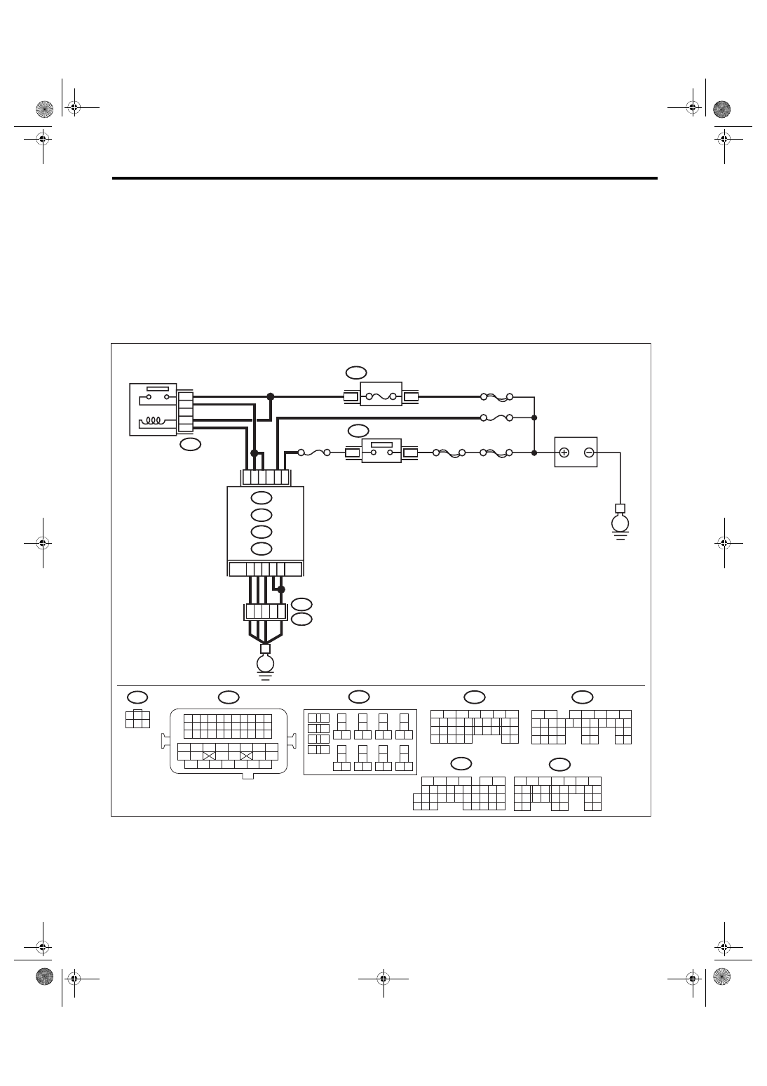
C: CHECK POWER SUPPLY AND GROUND LINE OF ENGINE CONTROL MOD-
ULE (ECM)
CAUTION:
After servicing or replacing faulty parts, perform Clear Memory Mode <Ref. to EN(H4DOTC)(diag)-63,
OPERATION, Clear Memory Mode.>, and Inspection Mode <Ref. to EN(H4DOTC)(diag)-49, PROCE-
WIRING DIAGRAM:
• Engine electrical system, without SI-DRIVE <Ref. to WI-32, WITHOUT SI-DRIVE, WIRING DIAGRAM,
• Engine electrical system, with SI-DRIVE <Ref. to WI-48, WITH SI-DRIVE, WIRING DIAGRAM, Engine
ECM
EN-08715
B136
C:
B72
C1
D7
B13
A3
A6
C2 C30
24
23
22
21
B134
B135
A:
C: B136
D: B137
B:
35
34
40
A4
D3
36
B134
B135
B137
B21
B72
A:
B:
D:
D1
3
1
15A
B220
B220
B220
3
4
18
19
6
7
4
3
5
2
1
12
11
10
9
8
40
36 39
38
37
34
33
35
32
28 31
30
29
23
22
21
20
26
25
24
27
17
16
15
14
13
2
6
5
4
3
1
54
52 53
50 51
48 49
46 47
45
44
42 43
40 41
38 39
36 37
34 35
33
32
31
30
29
28
27
26
25
24
23
22
21
20
11
10
9
19
18
17
16
8
7
6
5
15
14
13
12
4
3
2
1
31
30
29
28
27
21
20
19
18
17
16
26
25
24
15
14
13
12
11
23
22
10
3
4
9
1
2
8
7
6
5
35
34
33
32
31
30
29
21
20
19
18
17
16
28
27
26
15
14
13
12
11
25
23
22
24
10
3
4
9
1
2
8
7
6
5
31
30
32
29
34
33
21
20
19
18
17
16
28
27
26
15
14
13
12
11
25
23
22
24
10
3
4
9
1
2
8
7
6
5
B21
E2
35
27
16
10 11 12 13 14 15
25
24
30
9
8
7
17 18 19 20
28
21 22 23
29
32
31
1
2
3
4
5
6
26
33 34
E
E
SBF-7
SBF-6
FUSE
(RELAY BLOCK)
IGNITION
SWITCH
BATTERY
MAIN RELAY
No. 13
No. 12
MAIN SBF
EN(H4DOTC)(diag)-79
Diagnostics for Engine Starting Failure
ENGINE (DIAGNOSTICS)
Step
Check
Yes
No
1
CHECK MAIN RELAY.
1) Turn the ignition switch to OFF.
2) Remove the main relay.
3) Connect the battery to main relay terminals
No. 23 and No. 24.
4) Measure the resistance between main relay
terminals.
Terminals
No. 21 — No. 22:
Is the resistance less than 1 Ω? Go to step
Replace the main
relay. <Ref. to
FU(STI)-60, Main
Relay.> <Ref. to
FU(w/o STI)-58,
Main Relay.>
2
CHECK GROUND CIRCUIT FOR ECM.
1) Disconnect the connector from ECM.
2) Measure the resistance of harness between
ECM connector and chassis ground.
Connector & terminal
(B134) No. 3 — Chassis ground:
(B134) No. 4 — Chassis ground:
(B134) No. 6 — Chassis ground:
(B137) No. 1 — Chassis ground:
(B137) No. 3 — Chassis ground:
Is the resistance less than 5 Ω? Go to step
Repair the harness
and connector.
NOTE:
In this case, repair
the following item:
• Open circuit of
harness between
ECM
connector
and engine ground
• Poor contact of
coupling connector
3
CHECK INPUT VOLTAGE OF ECM.
1) Turn the ignition switch to ON.
2) Measure the voltage between ECM connec-
tor and chassis ground.
Connector & terminal
(B136) No. 2 (+) — Chassis ground (–):
(B136) No. 30 (+) — Chassis ground (–):
Is the voltage 10 V or more?
Repair the open or
ground short circuit
of harness of
power supply cir-
cuit.
4
CHECK INPUT VOLTAGE OF MAIN RELAY.
Measure the voltage between main relay con-
nector and chassis ground.
Connector & terminal
(B220) No. 21 (+) — Chassis ground (–):
(B220) No. 23 (+) — Chassis ground (–):
Is the voltage 10 V or more?
Repair the open or
ground short circuit
of harness of
power supply cir-
cuit.
5
CHECK INPUT VOLTAGE OF ECM.
1) Turn the ignition switch to OFF.
2) Install the main relay.
3) Turn the ignition switch to ON.
4) Measure the voltage between ECM connec-
tor and chassis ground.
Connector & terminal
(B135) No. 13 (+) — Chassis ground (–):
Is the voltage 10 V or more?
Repair the open or
ground short circuit
of harness
between ECM con-
nector and main
relay connector.
6
CHECK INPUT VOLTAGE OF ECM.
1) Turn the ignition switch to OFF.
2) Connect the connector to ECM.
3) Turn the ignition switch to ON.
4) Measure the voltage between ECM connec-
tor and chassis ground.
Connector & terminal
(B136) No. 1 (+) — Chassis ground (–):
(B137) No. 7 (+) — Chassis ground (–):
Is the voltage 10 V or more?
Repair the harness
and connector.
NOTE:
In this case, repair
the following item:
• Open circuit in
harness between
ECM
connector
and main relay
connector
• Poor contact of
main relay connec-
tor
• Poor contact of
ECM connector
Нет комментариевНе стесняйтесь поделиться с нами вашим ценным мнением.
Текст