Subaru Impreza 3 / Impreza WRX / Impreza WRX STI. Service manual — part 211
EN(H4DOTC)(diag)-68
Malfunction Indicator Light
ENGINE (DIAGNOSTICS)
3) If the diagnostic system detects a misfire which
could damage the catalyst, the malfunction indica-
tor light will blink at a cycle of 1 Hz.
4) Turn the ignition switch to OFF and connect the
delivery (test) mode connector (A) located under
the glove box.
(1) When the ignition switch is turned to ON
(engine OFF), the malfunction indicator light il-
luminates.
(2) After the engine starts, malfunction indicator
light blinks in a cycle of 0.5 Hz. (During diagno-
sis)
(3) Malfunction indicator light blinks at a cycle of
3 Hz after diagnosis if there is no trouble. Mal-
function indicator light illuminates if faulty.
(1) ON
(2) OFF
(3) Ignition switch ON
(4) Engine start
(5) Misfire start
(6) 1 second
(2)
(1)
(3)
(4)
(5)
(6)
EN-01680
EN-06146
(A)
(1) ON
(2) OFF
(3) Ignition switch ON
(4) 1 second
EN-01681
(2)
(1)
(4)
(3)
EN(H4DOTC)(diag)-69
Malfunction Indicator Light
ENGINE (DIAGNOSTICS)
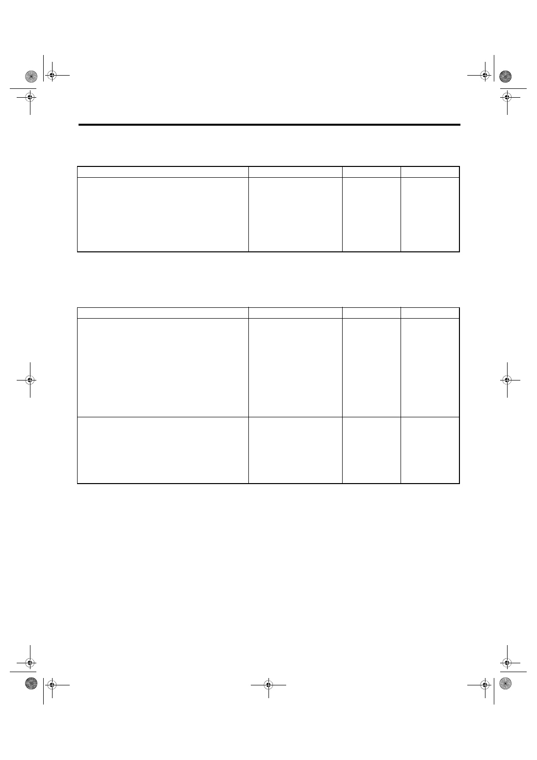
C: MALFUNCTION INDICATOR LIGHT DOES NOT COME ON
TROUBLE SYMPTOM:
When the ignition switch is turned to ON (engine OFF), malfunction indicator light does not illuminate.
D: MALFUNCTION INDICATOR LIGHT DOES NOT GO OFF
TROUBLE SYMPTOM:
Although malfunction indicator light comes on when the engine runs, DTC is not shown on the Subaru Select
Monitor or general scan tool display.
Step
Check
Yes
No
1
CHECK DTC.
Replace the meter
case assembly of
combination
meter. <Ref. to IDI-
16, Combination
Meter.>
Step
Check
Yes
No
1
CHECK DTC.
2
CHECK COMBINATION METER.
Perform the self-diagnosis for combination
meter system. <Ref. to IDI-5, SELF-DIAGNO-
SIS, INSPECTION, Combination Meter Sys-
tem.>
Does the malfunction indicator
light illuminate and go off nor-
mally?
Replace the meter
case assembly of
combination
meter. <Ref. to IDI-
16, Combination
Meter.>
EN(H4DOTC)(diag)-70
Malfunction Indicator Light
ENGINE (DIAGNOSTICS)
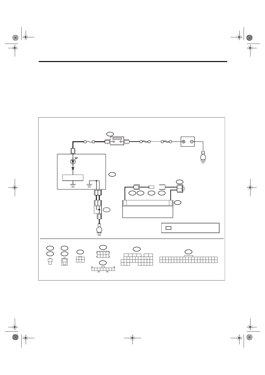
E: MALFUNCTION INDICATOR LIGHT DOES NOT BLINK
DIAGNOSIS:
• The malfunction indicator light circuit is open or shorted.
• The delivery (test) mode connector circuit is open.
TROUBLE SYMPTOM:
Malfunction indicator light does not blink during Inspection Mode.
WIRING DIAGRAM:
• Engine electrical system, without SI-DRIVE <Ref. to WI-32, WITHOUT SI-DRIVE, WIRING DIAGRAM,
• Engine electrical system, with SI-DRIVE <Ref. to WI-48, WITH SI-DRIVE, WIRING DIAGRAM, Engine
ECM
1
1
1
B76
B75
B364
B363
1
2
B364
B76
B75
1
2
B363
B122
3 4
5 6
1 2
7 8
2 3 4 5
1
6 7 8
i97
i10
1 2 3 4 5 6 7 8 9 10 11 12 13 14 15 16 17 18 19 20
21 22 23 24 25 26 27 28 29 30 31 32 33 34 35 36 37 38 39 40
21
*
**
22
i97
*
4
34
i10
2
B72
1
3
4 5 6
2
16
10 11 12 13 14 15
25
24
30
9
8
7
17 18 19 20
28
21 22 23
29
32
31
1
2
3
4
5
6
27
26
33 34 35
B136
B136
*
B122
1
B72
3
*
EN-09248
E
SBF-6
E
MAIN SBF
No. 5
IGNITION
SWITCH
BATTERY
DRIVE CIRCUIT
COMBINATION
METER
: TERMINAL No. OPTIONAL ARRANGEMENT
DELIVERY
(TEST)
MODE
CONNECTOR
TEST MODE
SUB
CONNECTOR
EN(H4DOTC)(diag)-71
Malfunction Indicator Light
ENGINE (DIAGNOSTICS)
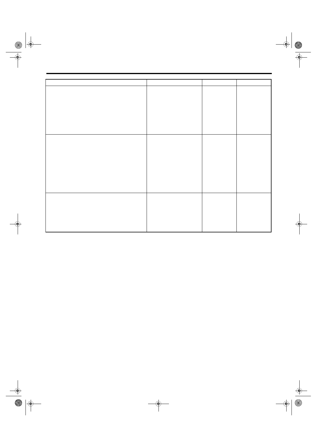
Step
Check
Yes
No
1
CHECK STATUS OF MALFUNCTION INDI-
CATOR LIGHT.
1) Turn the ignition switch to OFF.
2) Check the delivery (test) mode connector is
disconnected.
3) Turn the ignition switch to ON. (engine OFF)
Does the malfunction indicator
light illuminate?
2
CHECK HARNESS BETWEEN ECM AND DE-
LIVERY (TEST) MODE CONNECTOR.
1) Turn the ignition switch to OFF.
2) Disconnect the connector from ECM.
3) Connect the delivery (test) mode connector.
4) Measure the resistance of harness between
ECM connectors.
Connector & terminal
(B136) No. 34 — (B136) No. 4:
Is the resistance less than 1 Ω? Go to step
Repair the harness
and connector.
NOTE:
In this case, repair
the following item:
• Open circuit in
harness between
ECM connector
• Poor contact of
each
connector
between ECM con-
nector
3
CHECK FOR POOR CONTACT.
Check for poor contact of ECM connector.
Is there poor contact of ECM
connector?
Repair the poor
contact of ECM
connector.
Нет комментариевНе стесняйтесь поделиться с нами вашим ценным мнением.
Текст