Subaru Impreza 3 / Impreza WRX / Impreza WRX STI. Service manual — part 215
EN(H4DOTC)(diag)-84
Diagnostics for Engine Starting Failure
ENGINE (DIAGNOSTICS)
Step
Check
Yes
No
1
CHECK OPERATION OF EACH FUEL INJEC-
TOR.
While cranking the engine, check each fuel
injector emits operating sound. Use a sound
scope or attach a screwdriver to the injector for
this check.
Does the fuel injector emit
operating sound?
2
CHECK POWER SUPPLY TO EACH FUEL IN-
JECTOR.
1) Turn the ignition switch to OFF.
2) Disconnect the connector from fuel injector.
3) Turn the ignition switch to ON.
4) Measure the power supply voltage between
fuel injector connector and the engine ground.
Connector & terminal
#1 (E5) No. 1 (+) — Engine ground (–):
#2 (E16) No. 1 (+) — Engine ground (–):
#3 (E6) No. 1 (+) — Engine ground (–):
#4 (E17) No. 1 (+) — Engine ground (–):
Is the voltage 10 V or more?
Repair the harness
and connector.
NOTE:
In this case, repair
the following item:
• Open circuit in
harness between
main relay connec-
tor and fuel injector
connector
• Poor contact of
main relay connec-
tor
• Poor contact of
coupling connector
3
CHECK HARNESS BETWEEN ECM AND
FUEL INJECTOR CONNECTOR.
1) Turn the ignition switch to OFF.
2) Disconnect the connector from ECM.
3) Measure the resistance of harness between
ECM connector and fuel injector connector.
Connector & terminal
#1 (B134) No. 10 — (E5) No. 2:
#2 (B134) No. 11 — (E16) No. 2:
#3 (B134) No. 12 — (E6) No. 2:
#4 (B134) No. 13 — (E17) No. 2:
Is the resistance less than 1 Ω? Go to step
Repair the harness
and connector.
NOTE:
In this case, repair
the following item:
• Open circuit in
harness between
ECM
connector
and fuel injector
connector
• Poor contact of
coupling connector
4
CHECK HARNESS BETWEEN ECM AND
FUEL INJECTOR CONNECTOR.
Measure the resistance of harness between
ECM connector and chassis ground.
Connector & terminal
#1 (B134) No. 10 — Chassis ground:
#2 (B134) No. 11 — Chassis ground:
#3 (B134) No. 12 — Chassis ground:
#4 (B134) No. 13 — Chassis ground:
Is the resistance 1 MΩ or
more?
Repair the short
circuit to ground in
harness between
ECM connector
and fuel injector
connector.
5
CHECK EACH FUEL INJECTOR.
Measure the resistance between each fuel
injector terminals.
Terminals
No. 1 — No. 2:
Is the resistance 5 — 20 Ω?
6
CHECK FOR POOR CONTACT.
Check for poor contact of ECM connector.
Is there poor contact of ECM
connector?
Repair the poor
contact of ECM
connector.
EN(H4DOTC)(diag)-85
Diagnostic Procedure for Subaru Select Monitor Communication
ENGINE (DIAGNOSTICS)
18.Diagnostic Procedure for Subaru Select Monitor Communication
A: COMMUNICATION FOR INITIALIZING IMPOSSIBLE
DIAGNOSIS:
Open or short circuit in data link connector
TROUBLE SYMPTOM:
Subaru Select Monitor communication failure
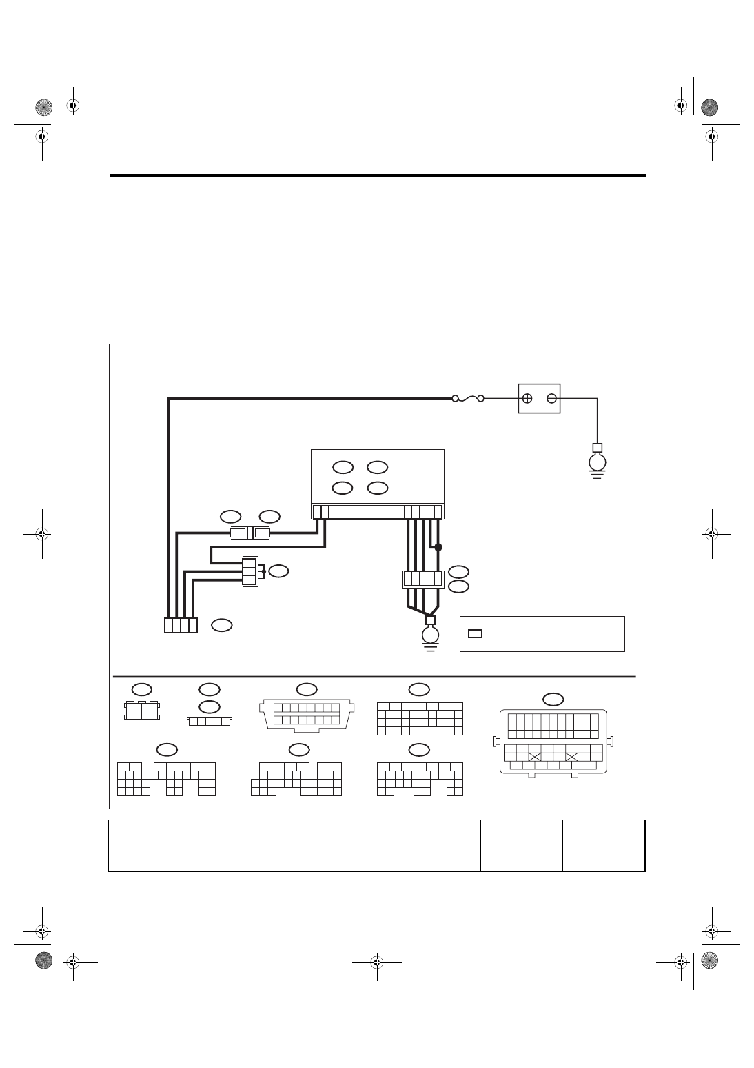
WIRING DIAGRAM:
• Engine electrical system, without SI-DRIVE <Ref. to WI-32, WITHOUT SI-DRIVE, WIRING DIAGRAM,
• Engine electrical system, with SI-DRIVE <Ref. to WI-48, WITH SI-DRIVE, WIRING DIAGRAM, Engine
Step
Check
Yes
No
1
CHECK POWER SUPPLY CIRCUIT.
Connect the SDI (Subaru Diagnosis Interface)
or general scan tool to data link connector.
Does SDI or general scan tool
turn ON?
ECM
B135
B:
35
34
33
32
31
30
29
21
20
19
18
17
16
28
27
26
15
14
13
12
11
25
23
22
24
10
3
4
9
1
2
8
7
6
5
B440
B442
2
2
1 2 3 4 5
B440
B442
35
34
40
36
C4
B14
D3
D1
A4
B135
B:
B134
A:
C: B136
D: B137
B21
E2
A6
A3
5
6
7
8
2
1
9
4
3
10
22 23
11 12 13 14 15
24 25
26
16 17
18 19 20 21
27
28 29
30 31
B137
D:
5
6
7
8
2
1
9
4
3
10
24
22 23
25
11 12 13 14 15
26 27
28
16 17
18 19 20 21
33 34
29
32
30 31
B134
A:
16
10 11 12 13 14 15
25
24
30
9
8
7
17 18 19 20
28
21 22 23
29
32
31
1
2
3
4
5
6
27
26
33 34 35
B136
C:
1 2 3 4
5 6 7 8
B122
*
*
*
B122
16
7
5
4
B40
B21
47
6
4
45
44
41
0
4
54
53
2
5
51
0
5
49
8
4
39
8
3
37
6
3
43
2
4
35
4
3
33
2
3
1
3
0
3
9
2
8
2
7
2
6
2
5
2
4
2
3
2
22
1
2
0
2
9
1
8
1
7
1
6
1
5
1
4
1
3
1
2
1
11
0
1
9
1 2 3 4 5 6 7 8
B40
16
15
14
13
12
11
10
9
8
7
6
5
4
3
2
1
*
EN-08719
E
E
: TERMINAL No. OPTIONAL ARRANGEMENT
No. 13
BATTERY
DATA LINK
CONNECTOR
EN(H4DOTC)(diag)-86
Diagnostic Procedure for Subaru Select Monitor Communication
ENGINE (DIAGNOSTICS)
2
CHECK POWER SUPPLY CIRCUIT.
Measure the voltage between data link connec-
tor and chassis ground.
Connector & terminal
(B40) No. 16 (+) — Chassis ground (–):
Is the voltage 10 V or more?
Repair the power
supply circuit.
NOTE:
In this case, repair
the following item:
• Open or ground
short circuit of har-
ness between bat-
tery and data link
connector
• Blown out of fuse
(M/B No. 13)
3
CHECK HARNESS BETWEEN DATA LINK
CONNECTOR AND CHASSIS GROUND.
1) Turn the ignition switch to OFF.
2) Measure the resistance of harness between
data link connector and chassis ground.
Connector & terminal
(B40) No. 4 — Chassis ground:
(B40) No. 5 — Chassis ground:
Is the resistance less than 5 Ω? Repair the poor
contact of data link
connector.
Repair the harness
and connector.
NOTE:
In this case, repair
the following item:
• Open circuit in
harness between
ECM
connector
and data link con-
nector
• Open circuit of
harness between
ECM
connector
and engine ground
• Poor contact of
ECM connector
• Poor contact of
coupling connector
4
CHECK HARNESS BETWEEN ECM AND
DATA LINK CONNECTOR.
1) Disconnect the connectors from ECM,
DCCD CM (6MT model only), VDC CM, airbag
CM, impact sensor, TPMS & keyless entry CM,
and body integrated unit.
CAUTION:
When disconnecting the connector from air-
bag CM, always follow the precautions on
AB section. <Ref. to AB-5, CAUTION, Gener-
al Description.>
2) Measure the resistance of harness between
ECM connector and data link connector.
Connector & terminal
(B135) No. 14 — (B40) No. 7:
Is the resistance less than 1 Ω? Go to step
Repair the harness
and connector.
NOTE:
In this case, repair
the following item:
• Open circuit in
harness between
ECM
connector
and data link con-
nector
• Poor contact of
coupling connector
5
CHECK HARNESS BETWEEN ECM AND
DATA LINK CONNECTOR.
Measure the resistance between data link con-
nector and chassis ground.
Connector & terminal
(B40) No. 7 — Chassis ground:
Is the resistance 1 MΩ or
more?
Repair the poor
contact of the ECM
or data link con-
nector.
Repair the short
circuit to ground in
harness between
ECM connector
and data link con-
nector.
Step
Check
Yes
No

EN(H4DOTC)(diag)-87
List of Diagnostic Trouble Code (DTC)
ENGINE (DIAGNOSTICS)
19.List of Diagnostic Trouble Code (DTC)
A: LIST
DTC
Item
Note
B1570
Antenna
<Ref. to IM(diag)-15, DTC B1570 ANTENNA, Diagnostic Procedure with Diagnostic
Trouble Code (DTC).>
B1571
Reference Code Incompatibility
B1572
IMM Circuit Failure (Except
Antenna Circuit)
B1574
Key Communication Failure
B1575
Incorrect Immobilizer Key
B1576
EGI Control Module EEPROM
B1577
IMM Control Module EEPROM
B1578
Meter Failure
P0011
Intake Camshaft Position - Tim-
ing Over-Advanced or System
Performance (Bank 1)
P0014
Exhaust AVCS System 1
(Range/Performance)
P0016
Crankshaft Position - Camshaft
Position Correlation (Bank1)
P0017
Crank and Cam Timing B Sys-
tem Failure (Bank 1)
P0018
Crankshaft Position - Camshaft
Position Correlation (Bank2)
P0019
Crank and Cam Timing B Sys-
tem Failure (Bank 2)
P0021
Intake Camshaft Position - Tim-
ing Over-Advanced or System
Performance (Bank 2)
P0024
Exhaust AVCS System 2
(Range/Performance)
P0030
HO2S Heater Control Circuit
(Bank 1 Sensor 1)
P0031
HO2S Heater Control Circuit
Low (Bank 1 Sensor 1)
P0032
HO2S Heater Control Circuit
High (Bank 1 Sensor 1)
P0037
HO2S Heater Control Circuit
Low (Bank 1 Sensor 2)
P0038
HO2S Heater Control Circuit
High (Bank 1 Sensor 2)
Нет комментариевНе стесняйтесь поделиться с нами вашим ценным мнением.
Текст