Subaru Impreza 3 / Impreza WRX / Impreza WRX STI. Service manual — part 202
EN(H4DOTC)(diag)-32
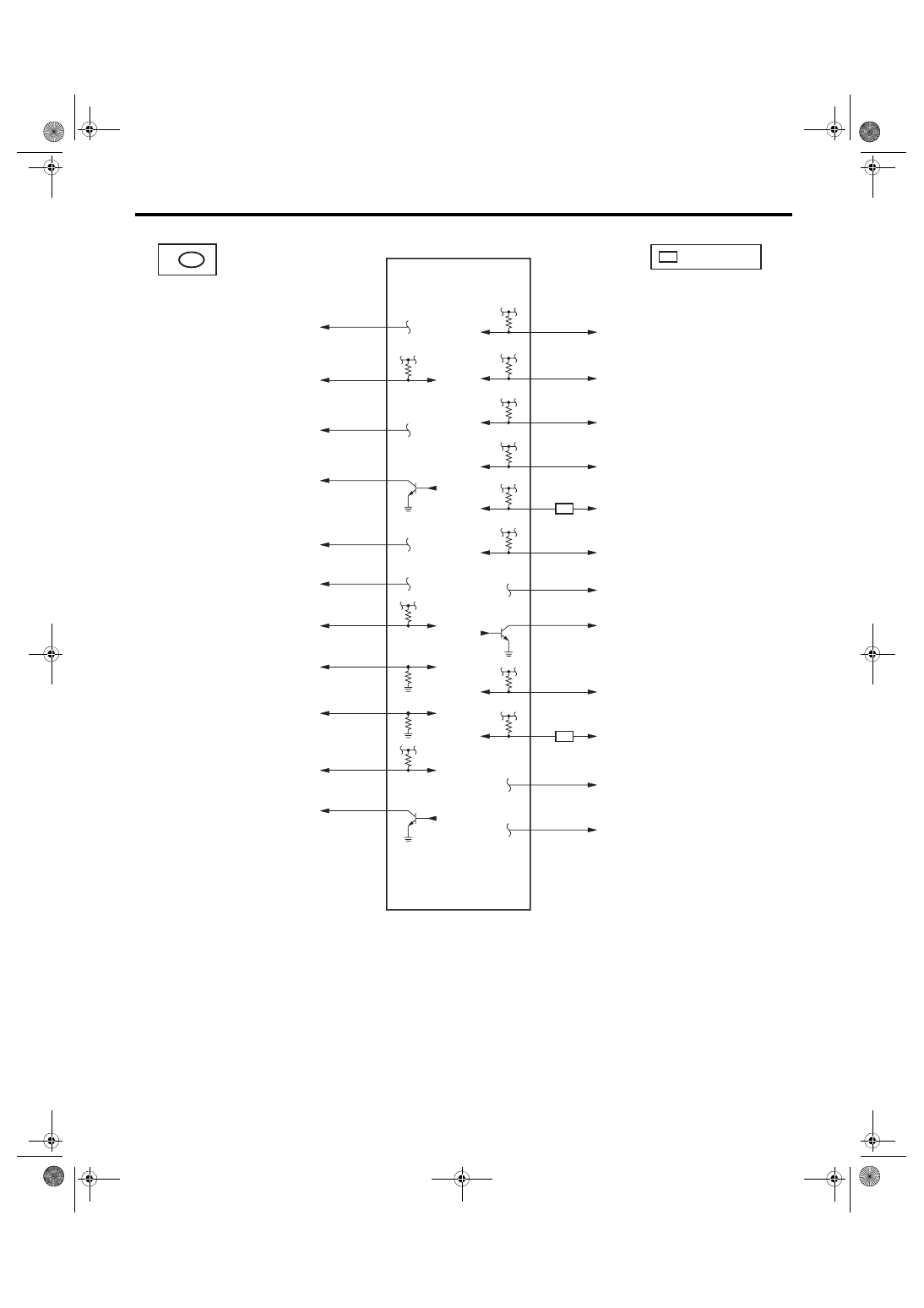
Engine Control Module (ECM) I/O Signal
ENGINE (DIAGNOSTICS)
D10
EN-09945
D6
D7
D1
D3
D2
D8
D22
D25
D30
D28
D31
D24
B137
D:
D20
D15
D11
D17
D27
D12
D9
D16
D23
D29
SI
SI
SI
ELCM
EXHAUST CAMSHAFT POSITION SENSOR LH
EXHAUST CAMSHAFT POSITION SENSOR RH
: WITH SI-DRIVE
INTAKE CAMSHAFT POSITION SENSOR LH
SECONDARY AIR COMBINATION VALVE
(WITH BUILT-IN PRESSURE SENSOR)
PCV HOSE ASSY
CRANKSHAFT POSITION SENSOR
TUMBLE GENERATOR VALVE ASSY RH
PURGE CONTROL SOLENOID VALVE 2
MANIFOLD ABSOLUTE PRESSURE SENSOR
INTAKE CAMSHAFT POSITION SENSOR RH
CRANKSHAFT POSITION SENSOR
(SHIELD)
POWER STEERING OIL PRESSURE SWITCH
EACH CAMSHAFT POSITION SENSOR
(GROUND)
CRANKSHAFT POSITION SENSOR
ENGINE COOLANT TEMPERATURE SENSOR
KNOCK SENSOR (SHIELD)
KNOCK SENSOR
ENGINE GROUND
ENGINE GROUND
MAIN RELAY
PURGE CONTROL SOLENOID VALVE 1
TUMBLE GENERATOR VALVE ASSY LH

EN(H4DOTC)(diag)-33
Engine Condition Data
ENGINE (DIAGNOSTICS)
6. Engine Condition Data
A: ELECTRICAL SPECIFICATION
Measuring condition:
• After engine is warmed up.
• Place the shift lever in neutral position.
• Turn the A/C to OFF.
• Turn all the accessory switches to OFF.
Content
Specifications
Engine load
17.6 — 35.64 (%): Idling
13.2 — 26.73 (%): 2,500 rpm racing
EN(H4DOTC)(diag)-34
Data Link Connector
ENGINE (DIAGNOSTICS)
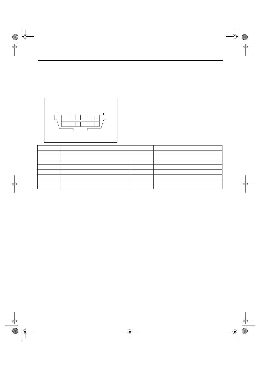
7. Data Link Connector
A: NOTE
This connector is used for Subaru Select Monitor.
CAUTION:
Do not connect any scan tools other than Subaru Select Monitor or general scan tool because the cir-
cuit for Subaru Select Monitor may be damaged.
1
2
3
4
5
7
6
8
9 10 11 12 13
15
14
16
EN-04893
Terminal No.
Content
Terminal No.
Content
1
Blank
9
Blank
2
Blank
10
Blank
3
Blank
11
Blank
4
Ground
12
Blank
5
Ground
13
Blank
6
CAN communication (Hi)
14
CAN communication (Lo)
7
Subaru Select Monitor signal
15
Blank
8
Blank
16
Power supply
EN(H4DOTC)(diag)-35
General Scan Tool
ENGINE (DIAGNOSTICS)
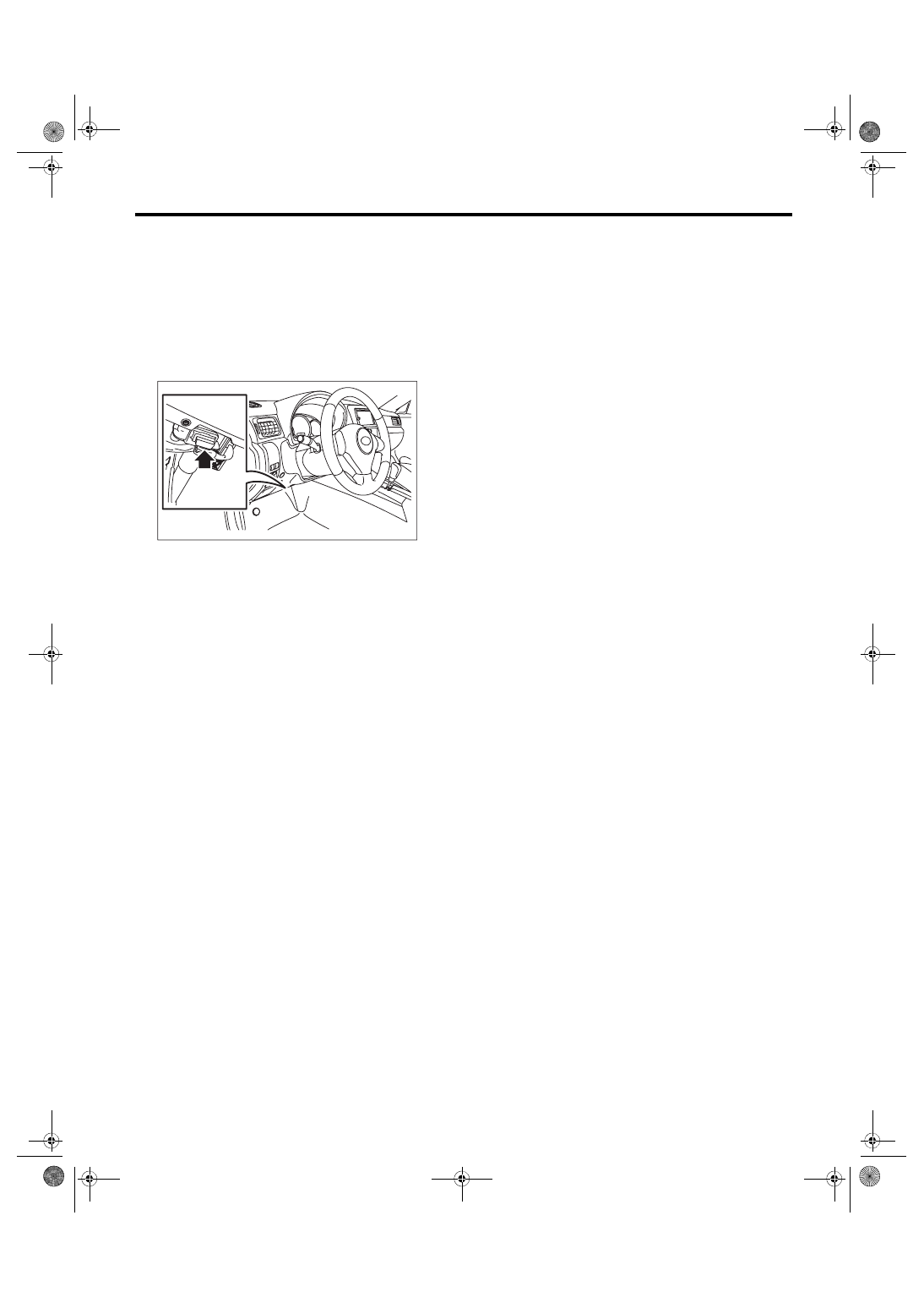
8. General Scan Tool
A: OPERATION
1. HOW TO USE GENERAL SCAN TOOL
1) Prepare a scan tool (general scan tool) required
by SAE J1978.
2) Connect the general scan tool to data link con-
nector located in the lower portion of the instrument
panel (on the driver’s side).
3) Using the general scan tool, call up each data.
General scan tool functions consist of:
(1) MODE $01: Current powertrain diagnostic
data
(2) MODE $02: Powertrain freeze frame data
(3) MODE $03: Emission-related powertrain
DTC
(4) MODE $04: Clear/Reset emission-related
diagnostic information
(5) MODE $06: Request on-board monitoring
test results for intermittently monitored systems
(6) MODE $07: Request on-board monitoring
test results for continuously monitored systems
(7) MODE $08: Request control for on-board
system, test, and component
(8) MODE $09: Request vehicle information
4) Read out the data according to repair proce-
dures. (For detailed operation procedure, refer to
the general scan tool operation manual.)
NOTE:
For details concerning DTC, refer to “List of Diag-
EN(H4DOTC)(diag)-87, List of Diagnostic Trouble
EN-06148
Нет комментариевНе стесняйтесь поделиться с нами вашим ценным мнением.
Текст