Subaru Impreza 3 / Impreza WRX / Impreza WRX STI. Service manual — part 200
EN(H4DOTC)(diag)-24
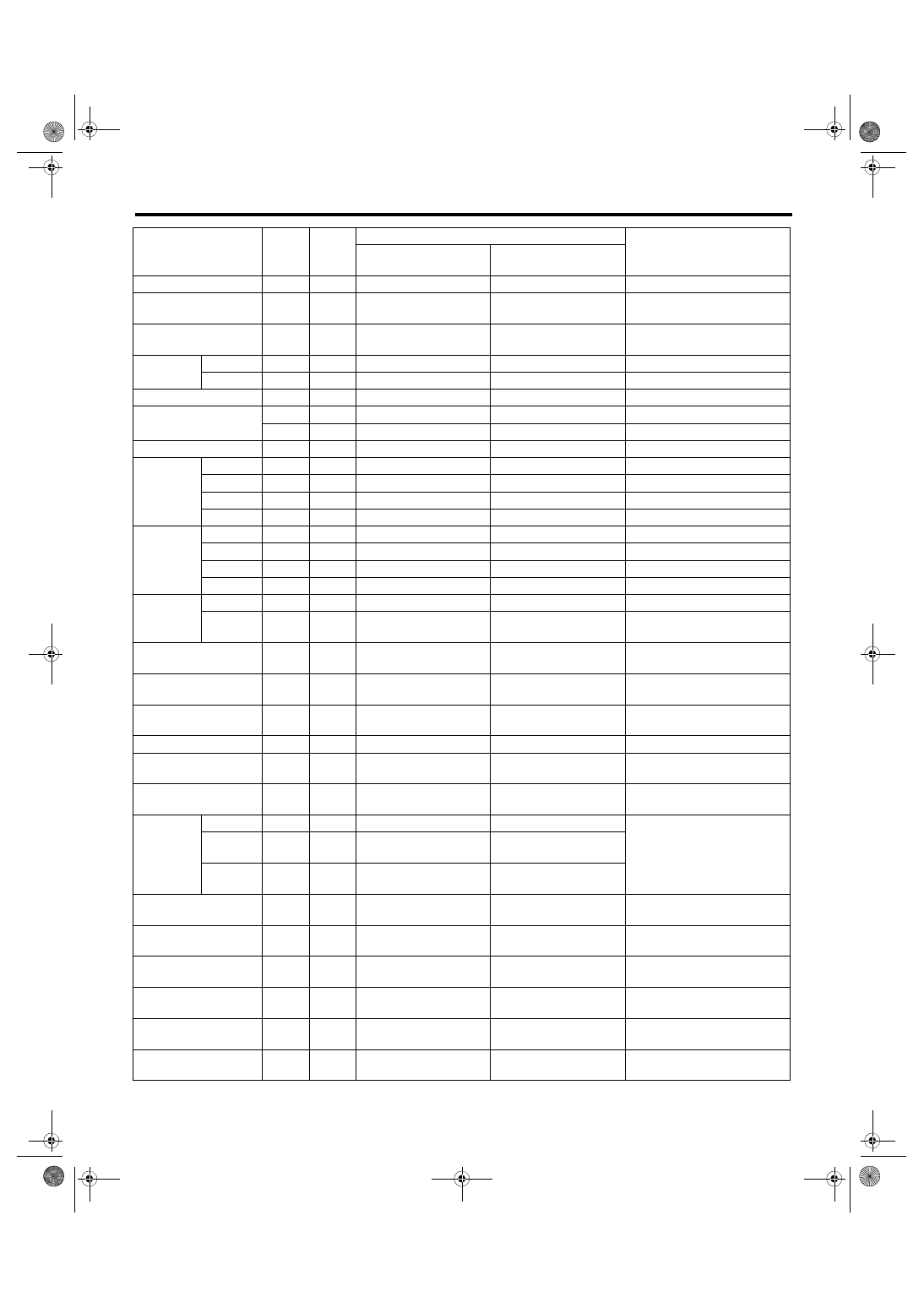
Engine Control Module (ECM) I/O Signal
ENGINE (DIAGNOSTICS)
Ignition switch
B136
30
10 — 13
12 — 14
—
Neutral position switch
B136
35
ON: 0
OFF: 10 — 13
ON: 0
OFF: 12 — 14
—
Delivery (test) mode
connector
B136
34
10 — 13
13 — 14
When connected: 0
Knock sen-
sor
Signal
B137
2
2.45 — 2.55
2.45 — 2.55
—
Shield
B137
8
0
0
—
Back-up power supply
B136
2
10 — 13
12 — 14
Ignition switch “OFF”: 10 — 13
Control module power
supply
B136
1
10 — 13
12 — 14
—
B137
7
10 — 13
12 — 14
—
Sensor power supply
B134
19
5
5
—
Ignition
control
#1
B134
21
0
0 or 5
Waveform
#2
B134
22
0
0 or 5
Waveform
#3
B134
31
0
0 or 5
Waveform
#4
B134
32
0
0 or 5
Waveform
Fuel injec-
tor
#1
B134
10
10 — 13
1 — 14
Waveform
#2
B134
11
10 — 13
1 — 14
Waveform
#3
B134
12
10 — 13
1 — 14
Waveform
#4
B134
13
10 — 13
1 — 14
Waveform
Fuel pump
control unit
Control
B136
33
0 or 5
0 or 5
Waveform
Diagnos-
tic signal
B135
10
10 — 13
12 — 14
—
A/C relay control
B135
35
ON: 0.5 or less
OFF: 10 — 13
ON: 0.5 or less
OFF: 12 — 14
—
Main fan relay control
B135
12
ON: 0.5 or less
OFF: 10 — 13
ON: 0.5 or less
OFF: 12 — 14
—
Sub fan relay control
B135
11
ON: 0.5 or less
OFF: 10 — 13
ON: 0.5 or less
OFF: 12 — 14
—
Engine speed output
B135
15
—
0 — 13 or more
Waveform
Purge control solenoid
valve 1
B137
6
ON: 1 or less
OFF: 10 — 13
ON: 1 or less
OFF: 12 — 14
Waveform
Purge control solenoid
valve 2
B137
15
ON: 1 or less
OFF: 10 — 13
ON: 1 or less
OFF: 12 — 14
Waveform
Manifold
absolute
pressure
sensor
Signal
B137
20
1.7 — 2.4
1.1 — 1.6
—
Power
supply
B134
19
5
5
Ground
(sensor)
B134
29
0
0
Power steering oil pres-
sure switch
B137
28
10 — 13
ON: 0
OFF: 12 — 14
—
SSM/GST communica-
tion line
B135
14
1 or less ←→ 4 or more
1 or less ←→ 4 or more
—
Intake camshaft posi-
tion sensor (LH)
B137
16
0 or 5
0 or 5
Waveform
Intake camshaft posi-
tion sensor (RH)
B137
24
0 or 5
0 or 5
Waveform
Exhaust camshaft posi-
tion sensor (LH)
B137
29
0 or 5
0 or 5
Models with SI-DRIVE
Waveform
Exhaust camshaft posi-
tion sensor (RH)
B137
23
0 or 5
0 or 5
Models with SI-DRIVE
Waveform
Description
Con-
nector
No.
Termi-
nal No.
Signal (V)
Note
Ignition SW ON
(engine OFF)
Engine ON
(idling)

EN(H4DOTC)(diag)-25
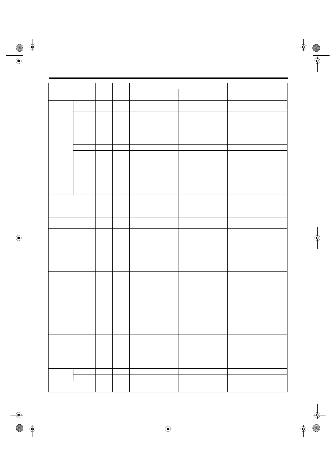
Engine Control Module (ECM) I/O Signal
ENGINE (DIAGNOSTICS)
Camshaft position sen-
sor ground
B137
30
0
0
—
Electronic
Throttle
Main
B134
18
Approx. 0.9
(After engine is warmed
up.)
Approx. 0.6 — 0.7
(After engine is warmed
up.)
Fully closed: Approx. 0.6
Fully open: Approx. 4.0
Sub
B134
28
Approx. 1.7
(After engine is warmed
up.)
Approx. 1.5 — 1.6
(After engine is warmed
up.)
Fully closed: Approx. 1.5
Fully open: Approx. 4.2
Power
supply
B134
19
5
5
—
Ground
(sensor)
B134
29
0
0
—
Electronic throttle con-
trol motor (+)
B134
2
Duty waveform
Duty waveform
Drive frequency: 500 Hz
Electronic throttle con-
trol motor (–)
B134
1
Duty waveform
Duty waveform
Drive frequency: 500 Hz
Electronic throttle con-
trol motor power supply
B135
7
10 — 13
12 — 14
—
Electronic throttle con-
trol motor relay
B135
17
ON: 0
OFF: 10 — 13
ON: 0
OFF: 12 — 14
When ignition switch is turned
to ON: ON
Intake oil
flow con-
trol sole-
noid valve
(LH)
Signal (+)
B134
17
ON: 10 — 13
OFF: 0
ON: 12 — 14
OFF: 0
—
Signal (–)
B134
16
0
0
—
Intake oil
flow con-
trol sole-
noid valve
(RH)
Signal (+)
B134
34
ON: 10 — 13
OFF: 0
ON: 12 — 14
OFF: 0
—
Signal (–)
B134
27
0
0
—
Exhaust oil
flow con-
trol sole-
noid valve
(LH)
Signal (+)
B134
5
ON: 10 — 13
OFF: 0
ON: 12 — 14
OFF: 0
Models with SI-DRIVE
Signal (–)
B134
14
0
0
Models with SI-DRIVE
Exhaust oil
flow con-
trol sole-
noid valve
(RH)
Signal (+)
B134
7
ON: 10 — 13
OFF: 0
ON: 12 — 14
OFF: 0
Models with SI-DRIVE
Signal (–)
B134
15
0
0
Models with SI-DRIVE
Description
Con-
nector
No.
Termi-
nal No.
Signal (V)
Note
Ignition SW ON
(engine OFF)
Engine ON
(idling)
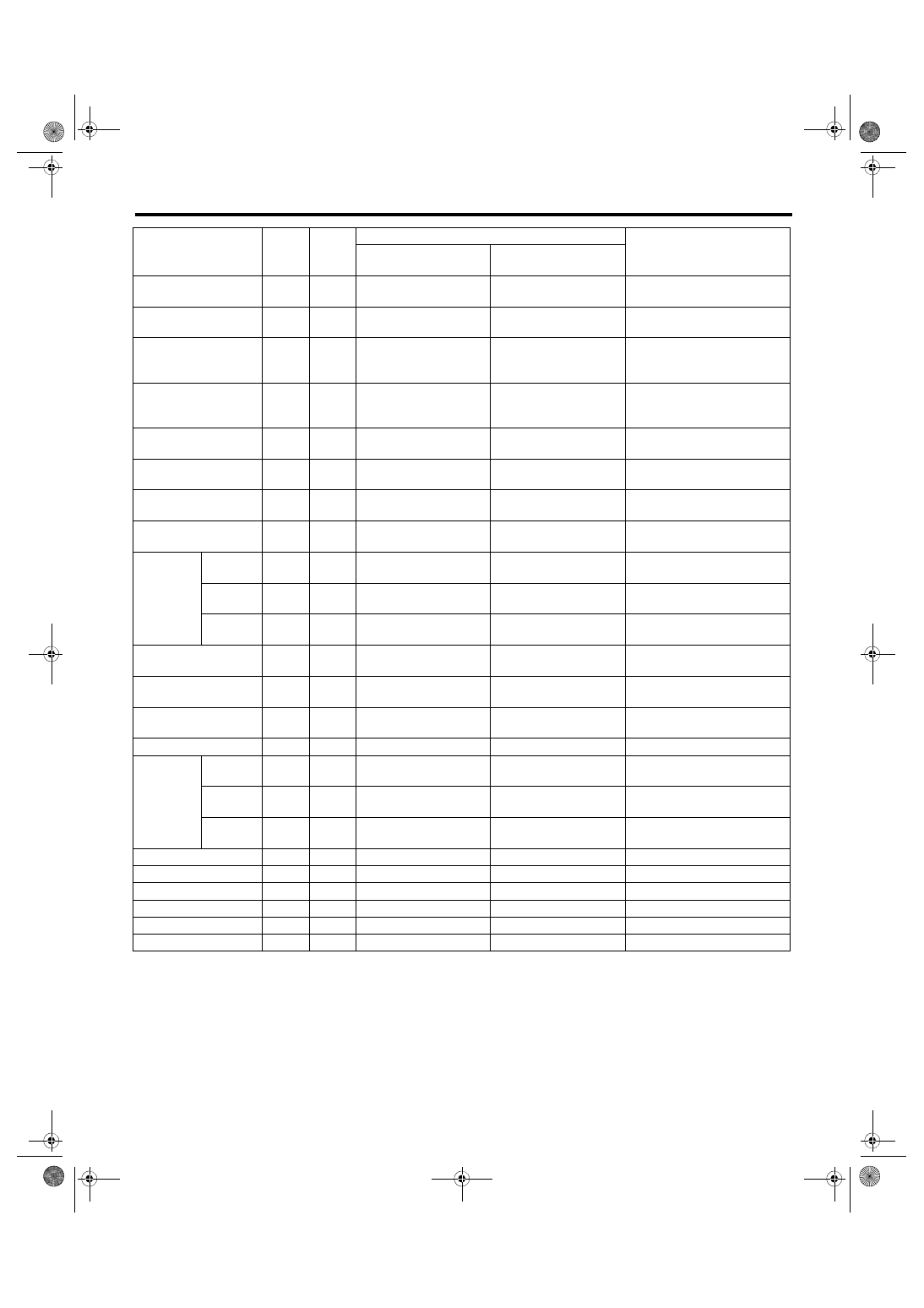
EN(H4DOTC)(diag)-26
Engine Control Module (ECM) I/O Signal
ENGINE (DIAGNOSTICS)
Accelera-
tor pedal
position
sensor
Main sen-
sor signal
B135
23
Fully closed: 0.4 — 1.0
Fully opened: 2.4 — 3.7
Fully closed: 0.4 — 1.0
Fully opened: 2.4 — 3.7
—
Main
power
supply
B135
21
5
5
—
Ground
(main
sensor)
B135
29
0
0
—
Shield
B136
4
0
0
—
Sub sen-
sor signal
B135
31
Fully closed: 0.3 — 1.1
Fully opened: 2.3 — 3.8
Fully closed: 0.3 — 1.1
Fully opened: 2.3 — 3.8
—
Sub
power
supply
B135
22
5
5
—
Ground
(sub sen-
sor)
B135
30
0
0
—
Starter relay
B135
26
ON: 0
OFF: 10 — 13
ON: 0
OFF: 12 — 14
ON: cranking
A/C middle pressure
switch
B136
7
ON: 0
OFF: 10 — 13
ON: 0
OFF: 12 — 14
—
Blower fan switch
B135
19
ON: 0
OFF: 10 — 13
ON: 0
OFF: 12 — 14
Manual A/C model
Clutch switch
B135
9
When clutch pedal is
depressed: 0
When clutch pedal is
released: 10 — 13
When clutch pedal is
depressed: 0
When clutch pedal is
released: 12 — 14
—
Brake switch 1
(brake switch)
B136
15
When brake pedal is
depressed: 0
When brake pedal is
released: 10 — 13
When brake pedal is
depressed: 0
When brake pedal is
released: 12 — 14
—
Brake switch 2
(stop light switch)
B136
3
When brake pedal is
depressed: 10 — 13
When brake pedal is
released: 0
When brake pedal is
depressed: 12 — 14
When brake pedal is
released: 0
—
Cruise control com-
mand switch
B136
12
When operating nothing:
3.5 — 4.5
When operating RES/
ACC: 2.5 — 3.5
When operating SET/
COAST: 0.5 — 1.5
When operating CAN-
CEL: 0 — 0.5
When operating nothing:
3.5 — 4.5
When operating RES/
ACC: 2.5 — 3.5
When operating SET/
COAST: 0.5 — 1.5
When operating CAN-
CEL: 0 — 0.5
—
Cruise control main
switch
B136
13
ON: 0
OFF: 5
ON: 0
OFF: 5
—
Fuel tank pressure sen-
sor
B136
21
2.3 — 2.7
2.3 — 2.7
—
Pressure control sole-
noid valve assembly
B135
3
ON: 1 or less
OFF: 10 — 13
ON: 1 or less
OFF: 12 — 14
—
Immobi-
lizer
Signal 1
B135
25
—
—
—
Signal 2
B135
24
—
—
—
CAN communication
(Hi)
B136
17
—
—
—
Description
Con-
nector
No.
Termi-
nal No.
Signal (V)
Note
Ignition SW ON
(engine OFF)
Engine ON
(idling)
EN(H4DOTC)(diag)-27
Engine Control Module (ECM) I/O Signal
ENGINE (DIAGNOSTICS)
CAN communication
(Lo)
B136
28
—
—
—
Blow-by leak diagnosis
B137
12
0
0
At the time of open circuit
(fault): 5
Tumble generator valve
position sensor signal
(RH)
B137
11
Fully closed: 0.4 — 1.2
Fully opened: 2.8 — 4.6
Fully closed: 0.4 — 1.2
Fully opened: 2.8 — 4.6
—
Tumble generator valve
position sensor signal
(LH)
B137
10
Fully closed: 0.4 — 1.2
Fully opened: 2.8 — 4.6
Fully closed: 0.4 — 1.2
Fully opened: 2.8 — 4.6
—
Tumble generator valve
(RH closed)
B134
26
0 or 10 — 13
0 or 12 — 14
—
Tumble generator valve
(LH closed)
B134
24
0 or 10 — 13
0 or 12 — 14
—
Tumble generator valve
(RH open)
B134
25
0 or 10 — 13
0 or 12 — 14
—
Tumble generator valve
(LH open)
B134
23
0 or 10 — 13
0 or 12 — 14
—
Secondary
air pipe
pressure
sensor
Signal
B137
9
2.2 — 2.8
2.2 — 2.8
When secondary air is
inducted: 3.2 — 4.9
Power
supply
B134
19
5.12
5.12
—
Ground
(sensor)
B134
29
0
0
—
Secondary air combi-
nation valve relay 1
B135
8
ON: 0
OFF: 10 — 13
ON: 0
OFF: 12 — 14
—
Secondary air combi-
nation valve relay 2
B135
20
ON: 0
OFF: 10 — 13
ON: 0
OFF: 12 — 14
—
Secondary air pump
relay
B135
27
ON: 0
OFF: 10 — 13
ON: 0
OFF: 12 — 14
—
Self-shutoff control
B135
13
10 — 13
12 — 14
—
ELCM
Switch-
ing valve
B135
4
10 — 13
12 — 14
Operating: 0
Pressure
sensor
B136
21
1 — 4
1 — 4
When ignition switch is turned
to ON: atmospheric pressure
Vacuum
pump
B137
27
10 — 13
12 — 14
Operating: 0
Ground (engine 1)
B134
6
0
0
—
Ground (engine 2)
B134
4
0
0
—
Ground (engine 3)
B134
3
0
0
—
Ground (engine 4)
B137
1
0
0
—
Ground (engine 5)
B137
3
0
0
—
Ground (body)
B136
4
0
0
—
Description
Con-
nector
No.
Termi-
nal No.
Signal (V)
Note
Ignition SW ON
(engine OFF)
Engine ON
(idling)
Нет комментариевНе стесняйтесь поделиться с нами вашим ценным мнением.
Текст