Subaru Impreza 3 / Impreza WRX / Impreza WRX STI. Service manual — part 510
DS-13
Propeller Shaft
DRIVE SHAFT SYSTEM
3. RUNOUT OF PROPELLER SHAFT
1) Remove the center exhaust pipe.
2) Remove the rear exhaust pipe and muffler.
3) Remove the heat shield cover.
4) Set the dial gauge with its indicator stem at the
center of the propeller shaft tube.
5) Turn the propeller shaft slowly by hands to check
for runout of the propeller shaft.
Runout:
Limit: 0.6 mm (0.024 in)
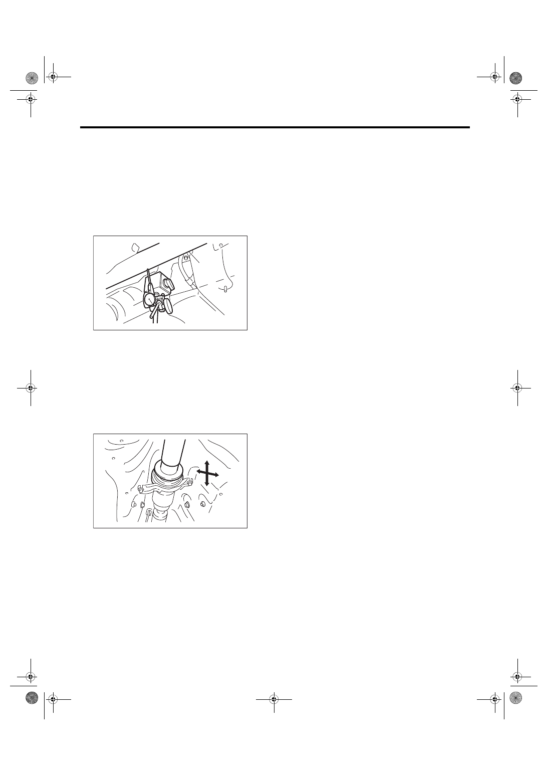
4. CENTER BEARING FREE PLAY
1) Remove the front and center exhaust pipes.
2) Remove the rear exhaust pipe and muffler.
3) Remove the heat shield cover.
4) Move the propeller shaft near the center bearing
up, down, left, right by hand, to check for any ab-
normal free play of the bearings.
(A) Propeller shaft
(B) Dial gauge
DS-00036
(B)
(A)
DS-00037
DS-14
Front Axle
DRIVE SHAFT SYSTEM
3. Front Axle
A: REMOVAL
1) Lift up the vehicle, and then remove the front
wheels.
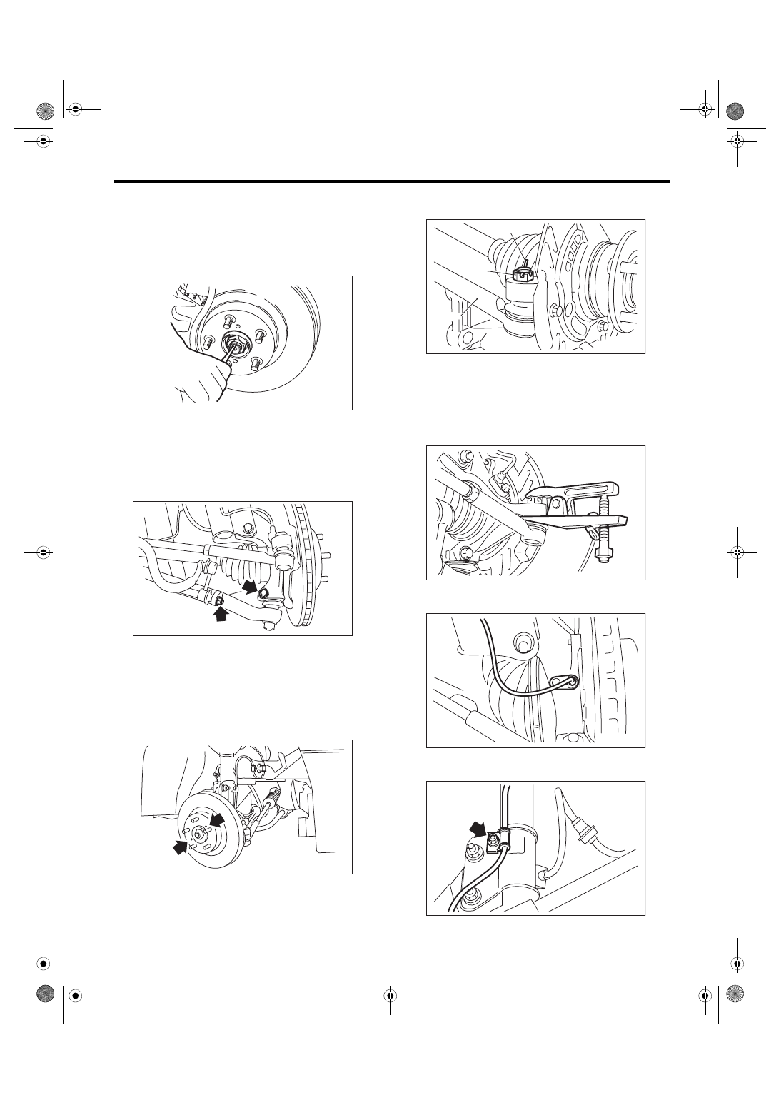
2) Lift the crimped section of axle nut.
3) Remove the axle nut using a socket wrench
while depressing the brake pedal.
CAUTION:
Do not loosen the axle nut while the front axle is
loaded. Doing so may damage the hub bearing.
4) Remove the stabilizer link.
5) Remove the disc brake caliper from the housing,
and suspend it from strut using a wire.
6) Remove the disc rotor from the hub.
NOTE:
If it is difficult to remove the disc rotor from the hub,
drive the 8 mm bolt into the threaded end of rotor,
and then remove the rotor.
7) Remove the cotter pin and castle nut securing
the tie-rod end to the housing knuckle arm.
8) Using a puller, remove the tie-rod ball joint from
knuckle arm.
9) Remove the ABS wheel speed sensor assembly
and harness.
10) Remove the bolts which secure the sensor har-
ness to the strut.
DS-00038
DS-00262
DS-00041
(A) Cotter pin
(B) Castle nut
(C) Tie-rod
DS-00042
(C)
(B)
(A)
DS-00043
DS-00249
DS-00144
DS-15
Front Axle
DRIVE SHAFT SYSTEM
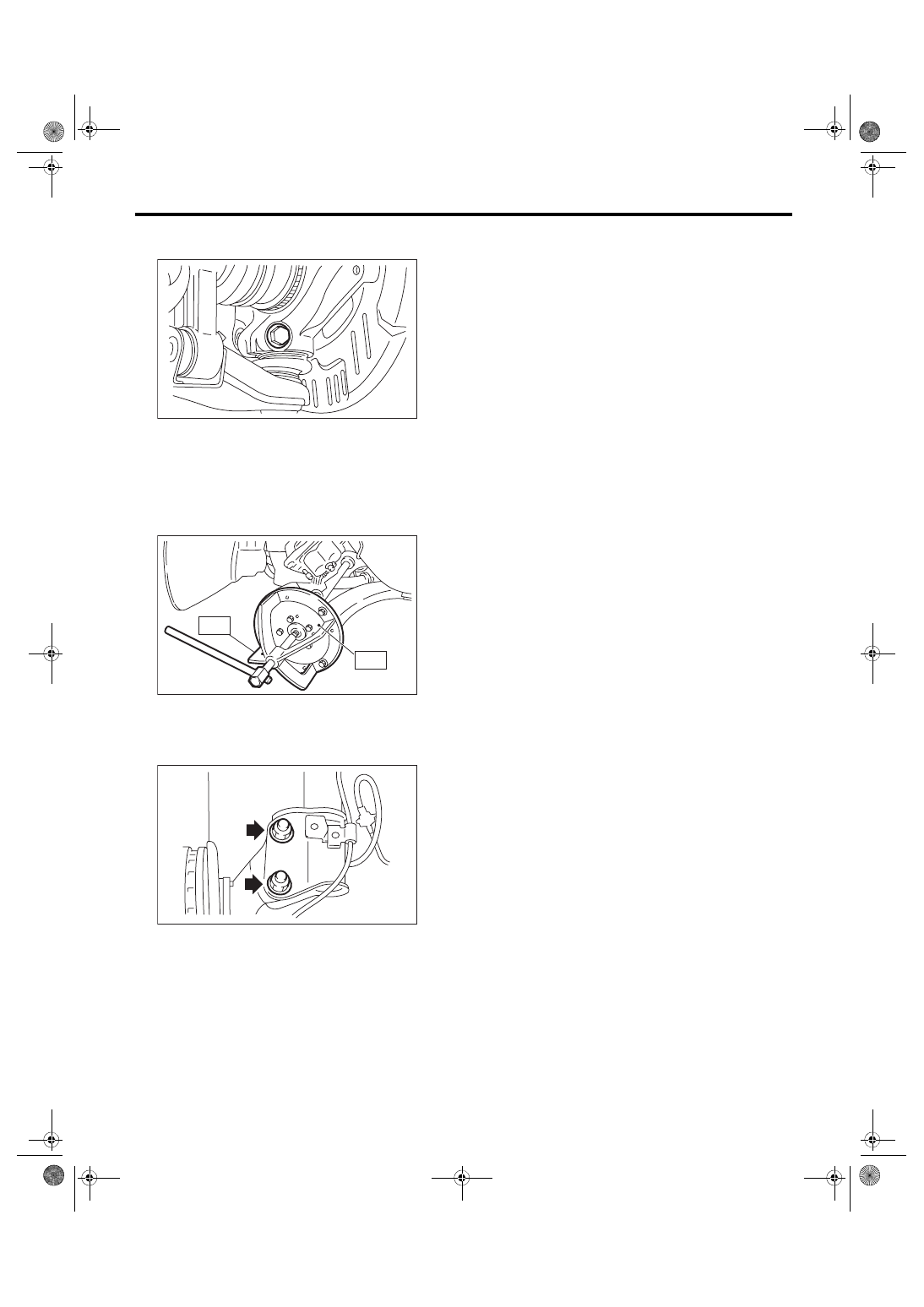
11) Remove the front arm ball joint from the hous-
ing.
12) Remove the front drive shaft from the transmis-
sion.
13) Remove the front drive shaft assembly from the
hub. If it is hard to remove, use the ST.
ST1 926470000
AXLE SHAFT PULLER
ST2 28099PA110
AXLE SHAFT PULLER
PLATE
14) After scribing an alignment mark on camber ad-
justing bolt head, remove the bolts which connect
the housing and strut, and disconnect the housing
from strut.
B: INSTALLATION
1) Align the alignment mark on the camber adjust-
ing bolt head, and tighten the housing and strut us-
ing a new flange nut.
Tightening torque:
155 N·m (15.81 kgf-m, 114.3 ft-lb)
2) Install the front drive shaft. <Ref. to DS-27, IN-
STALLATION, Front Drive Shaft.>
3) Install the front arm ball joint to the housing.
Tightening torque:
50 N·m (5.10 kgf-m, 36.9 ft-lb)
4) Install the ABS sensor harness to the strut.
5) Install the ABS wheel speed sensor on the hous-
ing.
Tightening torque:
7.5 N·m (0.76 kgf-m, 5.5 ft-lb)
6) Install the disc rotor to hub.
7) Install the disc brake caliper on the housing.
Tightening torque:
17-inch type
155 N·m (15.81 kgf-m, 114.3 ft-lb)
16-inch type
80 N·m (8.16 kgf-m, 59 ft-lb)
8) Install the stabilizer link.
CAUTION:
Use a new flange nut.
Tightening torque:
38 N·m (3.87 kgf-m, 28 ft-lb)
9) Connect the tie-rod end ball joint to the knuckle
arm with a castle nut.
CAUTION:
When connecting the tie-rod, do not hit the cap
at bottom of tie-rod end with a hammer.
Tightening torque:
27 N·m (2.75 kgf-m, 19.9 ft-lb)
DS-00045
DS-00145
ST2
ST1
DS-00046
DS-16
Front Axle
DRIVE SHAFT SYSTEM
10) Tighten the castle nut to specified torque and
tighten further within 60° until the pin hole is aligned
with the slot in the nut. Bend the cotter pin to lock.
11) While depressing the brake pedal, tighten a
new axle nut to the specified torque and lock it se-
curely.
CAUTION:
Do not apply weight to the front axle before
tightening the axle nut. Doing so may damage
the hub bearing.
Tightening torque:
220 N·m (22.43 kgf-m, 162.3 ft-lb)
12) After tightening the axle nut, lock it securely.
13) Install the wheel.
Tightening torque:
100 N·m (10.20 kgf-m, 73.8 ft-lb)
14) Connect the battery ground terminal.
15) Inspect the wheel alignment and adjust if nec-
essary.
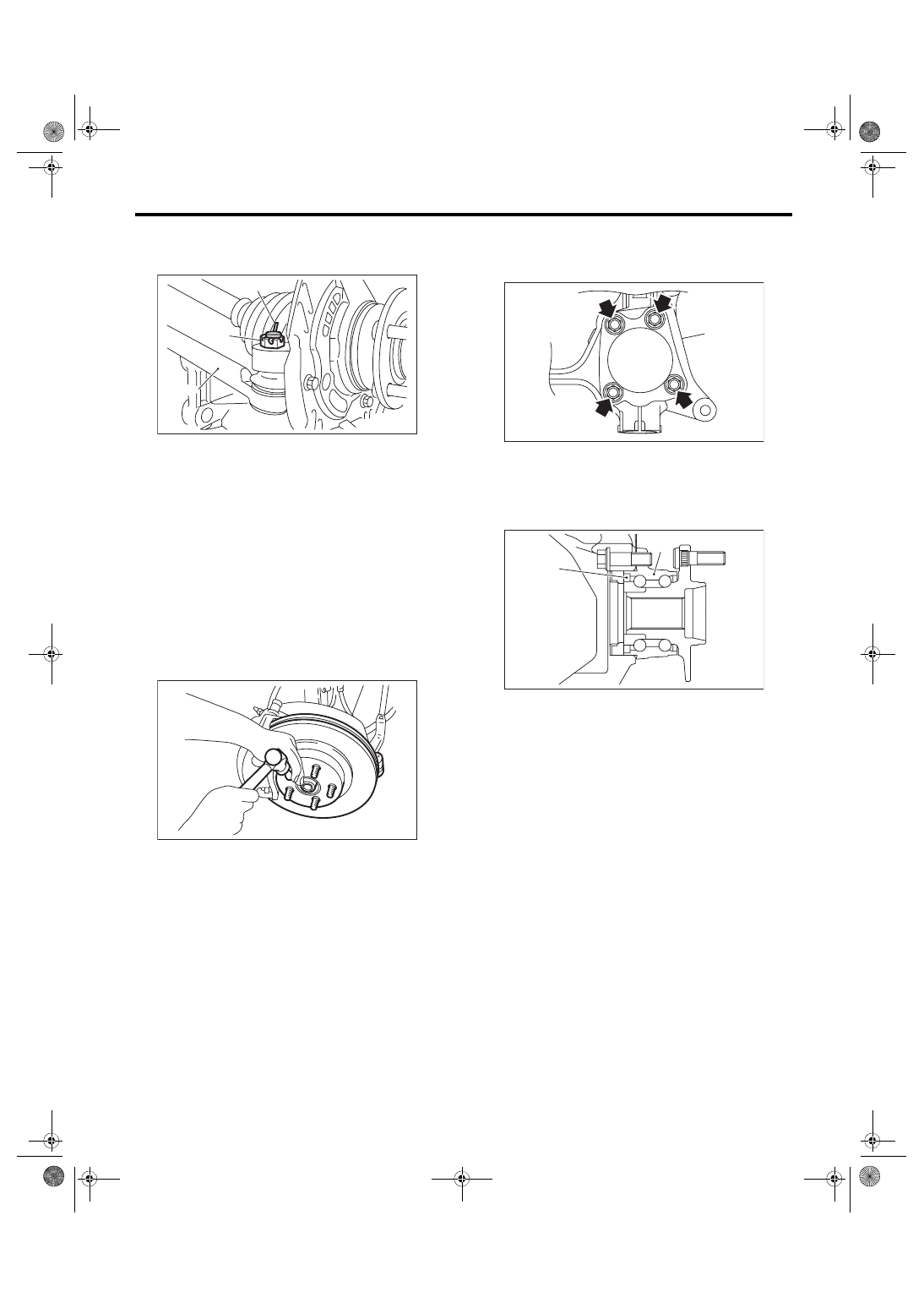
C: DISASSEMBLY
1) Remove the four bolts from the housing (A), and
remove the front hub unit bearing and disc cover.
CAUTION:
• Do not get closer the tool which charged
magnetism to magnetic encoder.
• Be careful not to damage the magnetic en-
coder.
2) Disassemble the front hub unit bearing. <Ref. to
DS-19, DISASSEMBLY, Front Hub Unit Bearing.>
(A) Cotter pin
(B) Castle nut
(C) Tie-rod
DS-00042
(C)
(B)
(A)
DS-00048
(1) Magnetic encoder
(2) Front hub unit bearing
DS-00231
(A)
DS-00250
(2)
(1)
Нет комментариевНе стесняйтесь поделиться с нами вашим ценным мнением.
Текст