Subaru Impreza 3 / Impreza WRX / Impreza WRX STI. Service manual — part 511
DS-17
Front Axle
DRIVE SHAFT SYSTEM
D: ASSEMBLY
1) Assemble the front hub unit bearing. <Ref. to
DS-19, ASSEMBLY, Front Hub Unit Bearing.>
2) Place the disc cover between housing (A) and
front hub unit, and tighten the four bolts.
Tightening torque:
65 N·m (6.63 kgf-m, 47.9 ft-lb)
CAUTION:
• Do not get closer the tool which charged
magnetism to magnetic encoder.
• Be careful not to damage the magnetic en-
coder.
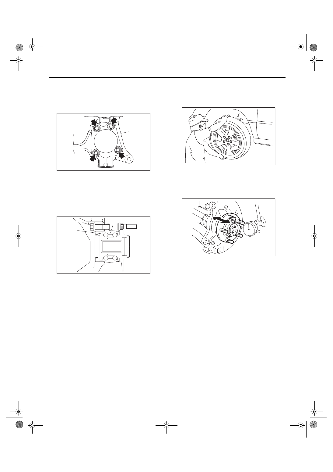
E: INSPECTION
1) Moving the front tire up and down by hand,
check there is no play in bearing, and check the
wheel rotates smoothly.
2) Inspect the lean of axis direction using a dial
gauge. Replace the bearing if the load range ex-
ceeds the limitation.
Service limit:
Maximum: 0.05 mm (0.0020 in)
(1) Magnetic encoder
(2) Front hub unit bearing
DS-00231
(A)
DS-00250
(2)
(1)
DS-00061
DS-00062
DS-18
Front Hub Unit Bearing
DRIVE SHAFT SYSTEM
4. Front Hub Unit Bearing
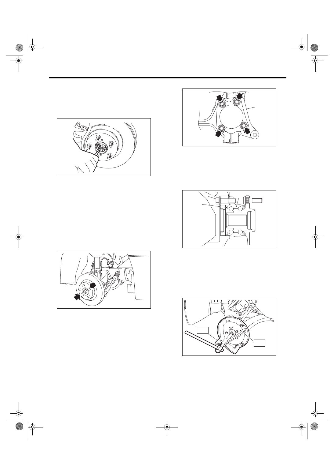
A: REMOVAL
1) Lift up the vehicle, and then remove the front
wheels.
2) Lift the crimped section of axle nut.
3) Remove the axle nut using a socket wrench
while depressing the brake pedal.
CAUTION:
Do not loosen the axle nut while the front axle is
loaded. Doing so may damage the hub bearing.
4) Remove the disc brake caliper from the housing,
and suspend it from strut using a wire.
5) Remove the disc rotor from the hub.
NOTE:
If it is difficult to remove the disc rotor from the hub,
drive the 8 mm bolt into the threaded end of rotor,
and then remove the rotor.
6) Remove the four bolts from the housing.
CAUTION:
• Do not get closer the tool which charged
magnetism to magnetic encoder.
• Be careful not to damage the magnetic en-
coder.
7) Remove the front hub unit bearing. If it is hard to
remove, use the ST.
ST1 926470000
AXLE SHAFT PULLER
ST2 28099PA110
AXLE SHAFT PULLER
PLATE
DS-00038
DS-00041
(A) Housing
(1) Magnetic encoder
(2) Front hub unit bearing
DS-00231
(A)
DS-00250
(2)
(1)
DS-00145
ST2
ST1
DS-19
Front Hub Unit Bearing
DRIVE SHAFT SYSTEM
B: INSTALLATION
1) Place the disc cover between housing (A) and
front hub unit, and tighten the four bolts.
Tightening torque:
65 N·m (6.63 kgf-m, 47.9 ft-lb)
2) Install the front drive shaft. <Ref. to DS-27, IN-
STALLATION, Front Drive Shaft.>
3) Tighten the axle nut temporarily.
4) Install the disc rotor to hub.
5) Install the disc brake caliper on the housing.
Tightening torque:
17-inch type
155 N·m (15.81 kgf-m, 114.3 ft-lb)
16-inch type
80 N·m (8.16 kgf-m, 59 ft-lb)
6) While depressing the brake pedal, tighten a new
axle nut to the specified torque and lock it securely.
CAUTION:
Do not apply weight to the front axle before
tightening the axle nut. Doing so may damage
the hub bearing.
Tightening torque:
220 N·m (22.43 kgf-m, 162.3 ft-lb)
7) After tightening the axle nut, lock it securely.
8) Install the wheel.
Tightening torque:
100 N·m (10.20 kgf-m, 73.8 ft-lb)
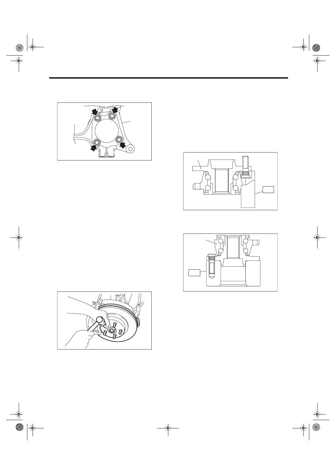
C: DISASSEMBLY
Using the ST and a hydraulic press, push out the
hub bolts.
CAUTION:
• Be careful not to hammer the hub bolts. This
may deform the hub.
• Do not reuse the hub bolt.
ST 28399AG000 HUB STAND
NOTE:
Since the hub unit bearing (1) can not be disassem-
bled, only hub bolts can be removed.
D: ASSEMBLY
1) Attach the hub to the ST securely.
ST 28099PA080 HUB STAND
2) Using a press, press the new hub bolts until their
seating surfaces contact the hub.
NOTE:
Use the 12 mm (0.47 in) dia. holes in the HUB
STAND to prevent bolts from tilting.
E: INSPECTION
Refer to “Front Axle” for inspection procedures.
<Ref. to DS-17, INSPECTION, Front Axle.>
CAUTION:
If there is any fault in the bearing, replace hub
unit bearing.
DS-00231
(A)
DS-00048
(1) Front hub unit bearing
DS-00252
ST
(1)
DS-00253
ST
(1)
DS-20
Rear Axle
DRIVE SHAFT SYSTEM
5. Rear Axle
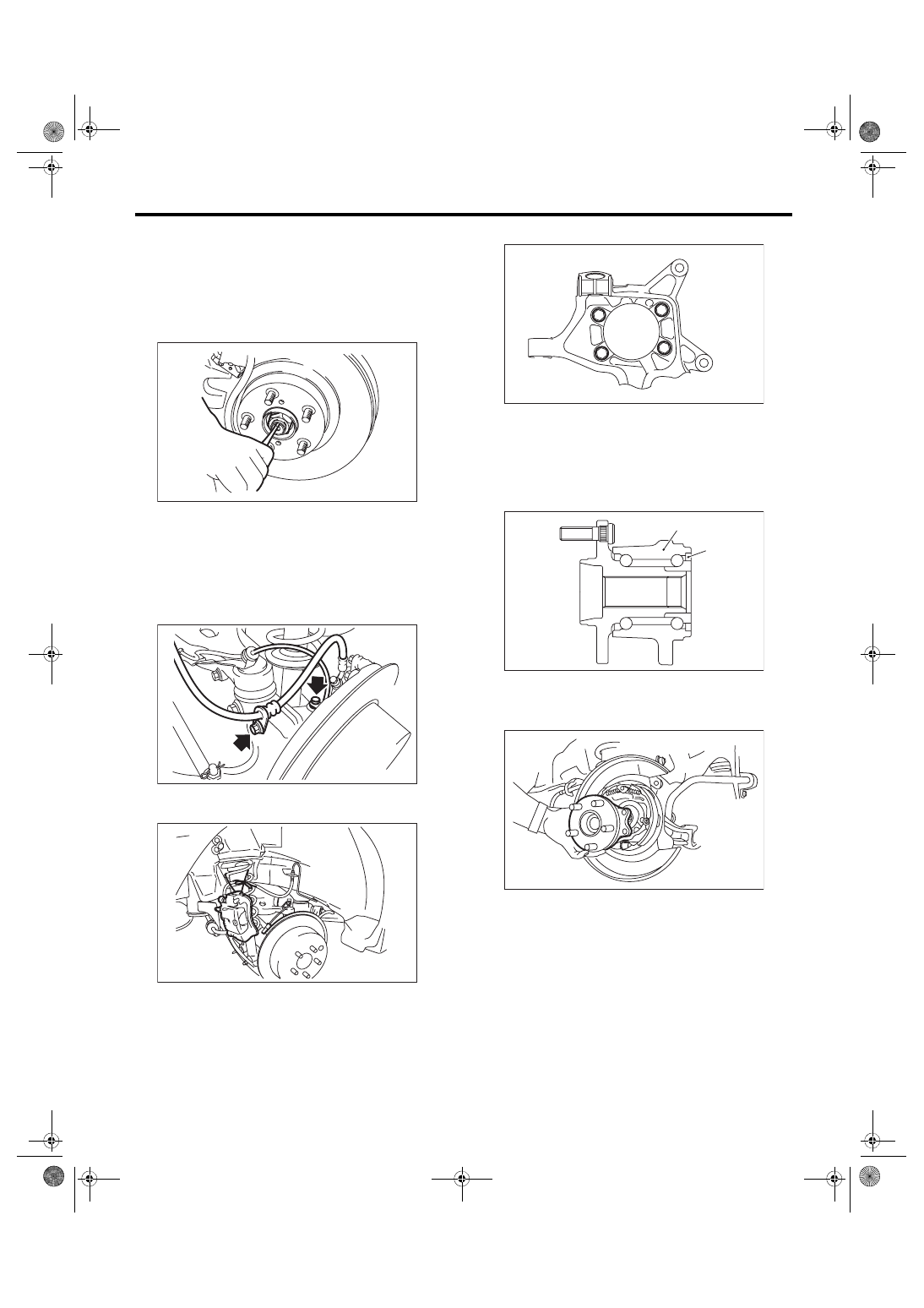
A: REMOVAL
1) Disconnect the ground cable from battery.
2) Lift up the vehicle, and then remove the rear
wheels.
3) Lift the crimped section of axle nut.
4) Remove the axle nut using a socket wrench
while depressing the brake pedal.
CAUTION:
Do not loosen the axle nut while the rear axle is
loaded. Doing so may damage the hub bearing.
5) Remove the brake hose bracket and the rear
ABS wheel speed sensor.
6) Remove the disc brake caliper from the rear
housing, and suspend it from vehicle using a string.
7) Remove the rear disc rotor.
8) Remove the four bolts from the rear housing.
9) Remove the rear hub unit bearing.
CAUTION:
• Be careful not to damage the magnetic en-
coder.
• Do not get closer the tool which charged
magnetism to magnetic encoder.
DS-00038
DS-00412
FU-03358
(1) Magnetic encoder
(2) Rear hub unit bearing
DS-00414
DS-00251
(2)
(1)
DS-00360
Нет комментариевНе стесняйтесь поделиться с нами вашим ценным мнением.
Текст