Subaru Impreza 3 / Impreza WRX / Impreza WRX STI. Service manual — part 791
LAN(diag)-73
Diagnostic Procedure with Diagnostic Trouble Code (DTC)
LAN SYSTEM (DIAGNOSTICS)
R: DTC U1321 CAN-LS METER NO-RECEIVE DATA
DTC DETECTING CONDITION:
Not received data from meter.
TROUBLE SYMPTOM:
Engine may not be started.
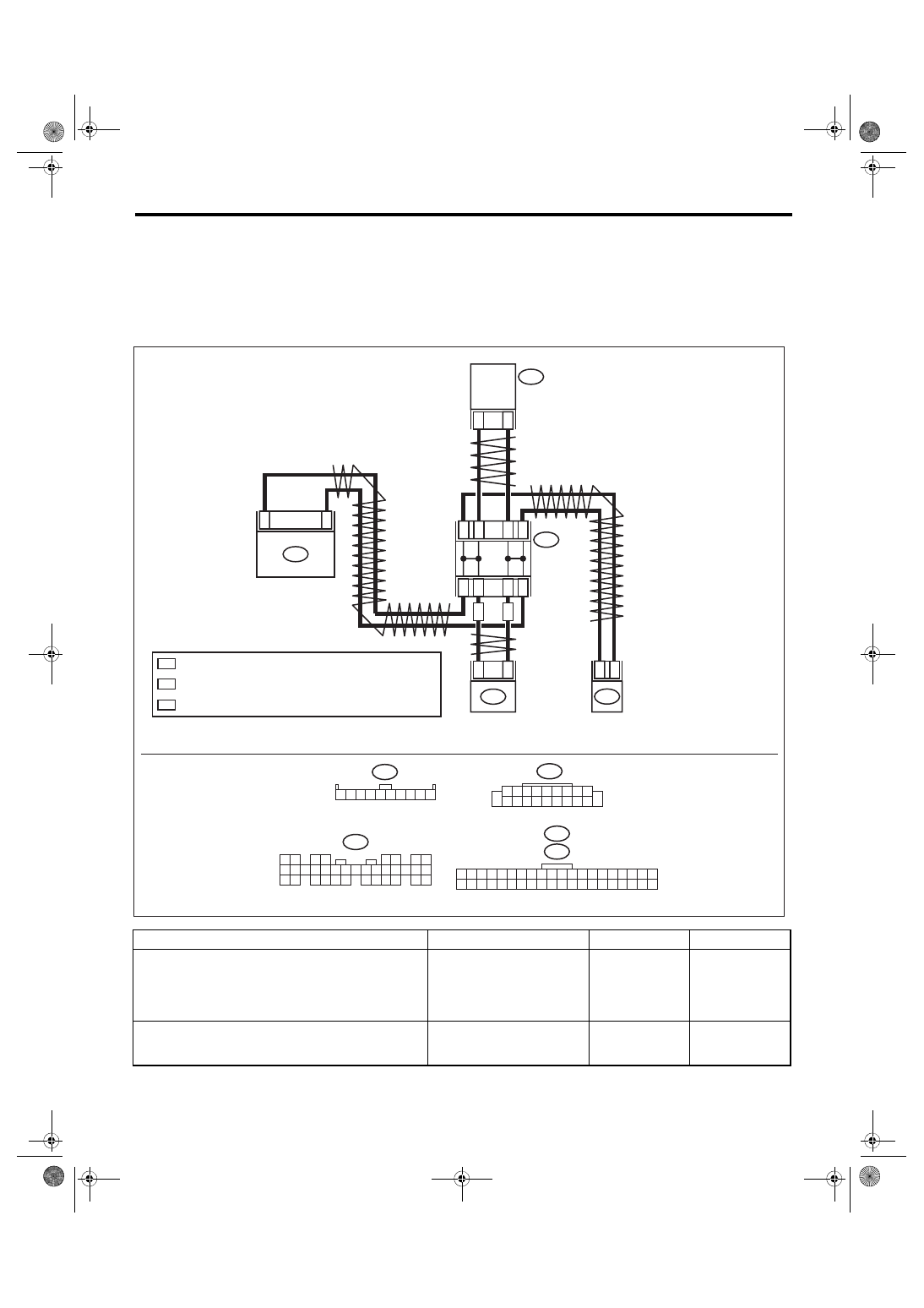
WIRING DIAGRAM:
CAN communication system <Ref. to WI-171, WIRING DIAGRAM, CAN Communication System.>
Step
Check
Yes
No
1
Is U1300 or U1302 displayed? Perform the diag-
nosis according to
DTC.
2
CHECK DTC.
Read the DTC of body integrated unit using
Subaru Select Monitor.
Is U1321 a current malfunc-
tion?
2
*
1
*
i84
1 2
3 4
5 6
7 8
9 10 11 12
14 15 16 17 18 19 20 21 22 23
24 25
26 27 28 29
30 31 32 33
34 35
13
i88
i10
1 2 3 4 5 6 7 8 9 10 11 12 13 14 15 16 17 18 19 20
21 22 23 24 25 26 27 28 29 30 31 32 33 34 35 36 37 38 39 40
i77
1 2 3 4 5 6 7 8 9 10
i85
1 2 3 4 5 6 7 8 9
10 11 12 13 14 15 16 17 18 19 20
2
*
2
*
2
*
2
*
1
*
1
*
1
*
1
*
11
12
AA
AA
AA
20
i85
i88
19
27
i10
26
i77
i84
1
9
LAN01360
BODY
INTEGRATED
UNIT
CAN JOINT
CONNECT
OR
COMBINATION
METER
AUDIO
: AUTO A/C
A/C
CONTROL
PANEL
: TERMINAL No. OPTIONAL ARRANGEMENT AMONG 1, 2, 3, 4 AND 5
: TERMINAL No. OPTIONAL ARRANGEMENT AMONG 6, 7, 8, 9 AND 10

LAN(diag)-74
Diagnostic Procedure with Diagnostic Trouble Code (DTC)
LAN SYSTEM (DIAGNOSTICS)
3
CHECK DTC.
1) Turn the ignition switch to OFF.
2) Disconnect all control module connectors
(i84, i10, i88, i85) that are connected to low
speed CAN communication line.
3) Connect the disconnected connectors.
4) Turn the ignition switch to ON.
5) Read the DTC of body integrated unit using
Subaru Select Monitor.
Is U1321 a current malfunc-
tion?
4
CHECK HARNESS.
1) Turn the ignition switch to OFF.
2) Disconnect all control module connectors
(i84, i10, i88, i85) that are connected to low
speed CAN communication line.
3) Using the tester, check for open, short
(power supply-output short, GND-output short)
in the harness.
Connector & terminal
(i84) No. 1 — (i10) No. 27 (combination
meter):
(i84) No. 9 — (i10) No. 26 (combination
meter):
(i84) No. 1 — (i88) No. 20 (auto A/C):
(i84) No. 9 — (i88) No. 19 (auto A/C):
(i84) No. 1 — (i85) No. 12 (audio):
(i84) No. 9 — (i85) No. 11 (audio):
Is harness normal?
Repair or replace
the harness.
5
CHECK COMBINATION METER.
1) Connect the disconnected connectors.
2) Perform the self-diagnosis of combination
meter. <Ref. to IDI-5, SELF-DIAGNOSIS,
INSPECTION, Combination Meter System.>
Is the self diagnosis normal?
Replace the com-
bination meter.
<Ref. to IDI-16,
REMOVAL, Com-
bination Meter.>
6
CHECK DTC.
1) Turn the ignition switch to OFF.
2) Disconnect all control module connectors
(i84, i10, i88, i85) that are connected to low
speed CAN communication line.
3) Connect the disconnected connectors.
4) Turn the ignition switch to ON.
5) Read the DTC of body integrated unit using
Subaru Select Monitor.
Is U1321 a current malfunc-
tion?
Replace the body
integrated unit.
<Ref. to SL-48,
REMOVAL, Body
Integrated Unit.>
7
CHECK HARNESS.
1) Turn the ignition switch to OFF.
2) Shake the harness used for low speed CAN
communication circuit.
3) Turn the ignition switch to ON.
4) Read the DTC of body integrated unit using
Subaru Select Monitor.
Is U1321 a current malfunc-
tion?
Repair the poor
contact, open cir-
cuit of harness or
replace harness.
8
CHECK CONNECTOR.
1) Turn the ignition switch to OFF.
2) Disconnect all control module connectors
(i84, i10, i88, i85) that are connected to low
speed CAN communication line.
Is there poor contact of connec-
tor terminal?
Repair the connec-
tor terminal, or
replace harness.
It is possible that
temporary poor
communication
occurs.
Step
Check
Yes
No
LAN(diag)-75
Diagnostic Procedure with Diagnostic Trouble Code (DTC)
LAN SYSTEM (DIAGNOSTICS)
S: DTC B1500 KEYLESS UART COM. MALFUNCTION
DTC DETECTING CONDITION:
Open or short circuit in keyless UART circuit
TROUBLE SYMPTOM:
Door lock does not operate with keyless.
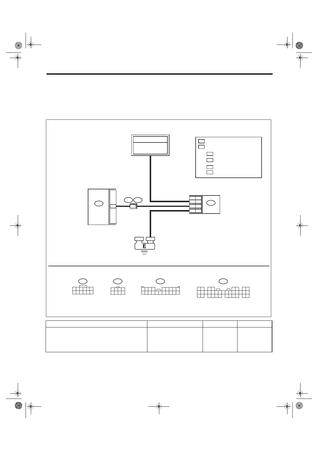
WIRING DIAGRAM:
Keyless entry system <Ref. to WI-159, WIRING DIAGRAM, Keyless Entry System.>
Step
Check
Yes
No
1
Is B1500 current malfunction? Go to step
R221
1 2 3 4 5 6
7 8 9 10 11 12
*
1
*
2
: R221
: R80
*
1
*
2
5
6
4
11
3
7
i102
R167
1
i102
1 2 3 4
5 6 7 8 9
10 11 12 13 14 15 16 17 18 19 20
i84
1 2
3 4
5 6
7 8
9 0
1
1
1
2
1
4
1
5
1
6
1
7
1
8
1
9
1
0
2
1
2
2
2
3
2
4
2
5
2
6
2
7
2
8
2
9
2
0
3
1
3
2
3
3
3
4
3
5
3
3
1
R80
2
1
3 4
5 6 7 8
i84
4
2
LAN00609
OT
TP
TP
:
OT
OT
TP
: OT
TP
TO POWER SUPPLY
CIRCUIT
BODY
INTEGRATED
UNIT
: WITH TPMS
: WITHOUT TPMS
: KEYLESS ENTRY CM
: TPMS & KEYLESS ENTRY CM
FB-11
M/B FUSE NO. 8
(B)

LAN(diag)-76
Diagnostic Procedure with Diagnostic Trouble Code (DTC)
LAN SYSTEM (DIAGNOSTICS)
2
CHECK DTC.
1) Turn the ignition switch to OFF.
2) Disconnect the connectors from body inte-
grated unit and keyless entry control module.
3) Connect the disconnected connectors.
4) Turn the ignition switch to ON.
5) Read the DTC of body integrated unit using
Subaru Select Monitor.
Is B1500 current malfunction? Go to step
3
CHECK HARNESS.
1) Turn the ignition switch to OFF.
2) Disconnect the connectors from body inte-
grated unit and keyless entry control module.
3) Using the tester, check for open, short
(power supply-output short, GND-output short)
in the harness.
Connector & terminal
Keyless entry CM
(i84) No. 24 — (R80) No. 3:
TPMS & keyless entry CM
(i84) No. 24 — (R221) No. 11:
Is harness normal?
Repair or replace
the harness.
4
CHECK HARNESS.
Using the tester, measure the voltage between
keyless entry control module and chassis
ground.
Connector & terminal
Keyless entry CM
(R80) No. 4 (+) — Chassis ground (–):
TPMS & keyless entry CM
(R221) No. 6 (+) — Chassis ground (–):
Is the voltage battery voltage? Go to step
Check the power
supply circuit for
keyless entry con-
trol module.
5
CHECK HARNESS.
Using the tester, measure the resistance
between keyless entry control module and
chassis ground.
Connector & terminal
Keyless entry CM
(R80) No. 7 — Chassis ground:
TPMS & keyless entry CM
(R221) No. 5 — Chassis ground:
Is the resistance less than 10
Ω?
Repair or replace
the open circuit of
harness.
6
CHECK OPERATION.
1) Install the keyless entry control module from
other vehicle, which is working normally.
2) Register the keyless key which is working
normally.
3) Operate the keyless key.
Does the door locking operate? Replace the key-
less entry control
module. <Ref. to
SL-46, REMOVAL,
Keyless Entry Con-
trol Module.>
Replace the body
integrated unit.
<Ref. to SL-48,
REMOVAL, Body
Integrated Unit.>
7
CHECK CONNECTOR.
Disconnect the connectors from body inte-
grated unit and keyless entry control module.
Is there poor contact of connec-
tor?
Repair the connec-
tor, or replace har-
ness.
Temporary com-
munication failure
occurs.
Step
Check
Yes
No
Нет комментариевНе стесняйтесь поделиться с нами вашим ценным мнением.
Текст