Subaru Impreza 3 / Impreza WRX / Impreza WRX STI. Service manual — part 557
BR-13
General Description
BRAKE
C: CAUTION
• Wear appropriate work clothing, including a helmet, protective goggles and protective shoes when per-
forming any work.
• Before removal, installation or disassembly, be sure to clarify the failure. Avoid unnecessary removal, in-
stallation, disassembly and replacement.
• Use SUBARU genuine grease etc. or equivalent. Do not mix grease etc. of different grades or manufac-
turers.
• Before securing a part on a vise, place cushioning material such as wood blocks, aluminum plate, or cloth
between the part and the vise.
• Be sure to tighten fasteners including bolts and nuts to the specified torque.
• Place shop jacks or rigid racks at the specified points.
D: PREPARATION TOOL
1. GENERAL TOOL
TOOL NAME
REMARKS
Snap ring pliers
Used for removing and installing snap rings.
BR-14
Front Brake Pad
BRAKE
2. Front Brake Pad
A: REMOVAL
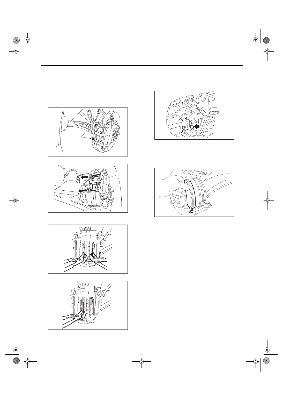
1. BREMBO TYPE
1) Lift up the vehicle, and then remove the front
wheels.
2) Remove clips (1).
3) Remove the pad pins (1) and cross spring (2).
4) Spread apart the pads using a pair of wrenches
and push back the piston.
5) Remove the pads.
2. EXCEPT FOR BREMBO TYPE
1) Lift up the vehicle, and then remove the front
wheels.
2) Remove the caliper bolt.
3) Raise the caliper body and support it.
NOTE:
Do not disconnect the brake hose from the caliper
body.
4) Remove the pads.
(1)
BR-00292
(1)
(2)
BR-00293
BR-00290
BR-00291
BR-00339
BR-00849
BR-15
Front Brake Pad
BRAKE
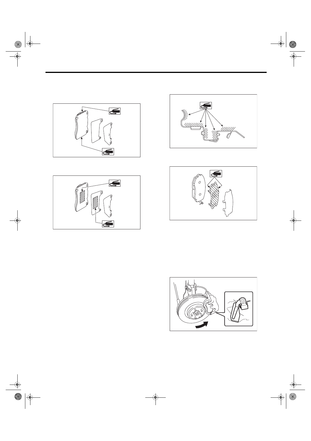
B: INSTALLATION
1. BREMBO TYPE
1) Apply a thin coat of Molykote M7439 or grease
contained in the pad kit to the pad side.
2) Apply a thin coat of Molykote AS880N (Part No.
K0777YA010) or grease contained in the pad kit to
the pad and pad shim.
3) Install the pads to the caliper body.
4) Install the cross spring.
5) Install the pad pins.
6) Install the clips.
2. EXCEPT FOR BREMBO TYPE
1) Apply a thin coat of Molykote M7439 or grease
contained in the pad kit to the pad clip.
2) Apply a thin coat of Molykote AS880N (Part No.
K0777YA010) or grease contained in the pad kit to
both surfaces of the pad and inner shim.
3) Install the pad to support.
CAUTION:
• Be sure to install so that the pad return
spring faces the input side of the direction of
brake rotor rotation, as shown in the figure.
• Correctly install the pad return spring to the
supporting surface of the pad clip as shown in
the figure.
• If the pad return spring is deformed or dam-
aged, replace the brake pad.
BR-00782
BR-00783
(1) Pad return spring
(2) Supporting surface of pad clip
(3) Direction of brake rotor rotation
BR-00596
BR-00837
BR-00885
(3)
(1)
(2)
BR-16
Front Brake Pad
BRAKE
NOTE:
Install the pad indicator in proper direction.
4) Install the caliper body to the support.
Tightening torque:
27 N·m (2.75 kgf-m, 19.9 ft-lb)
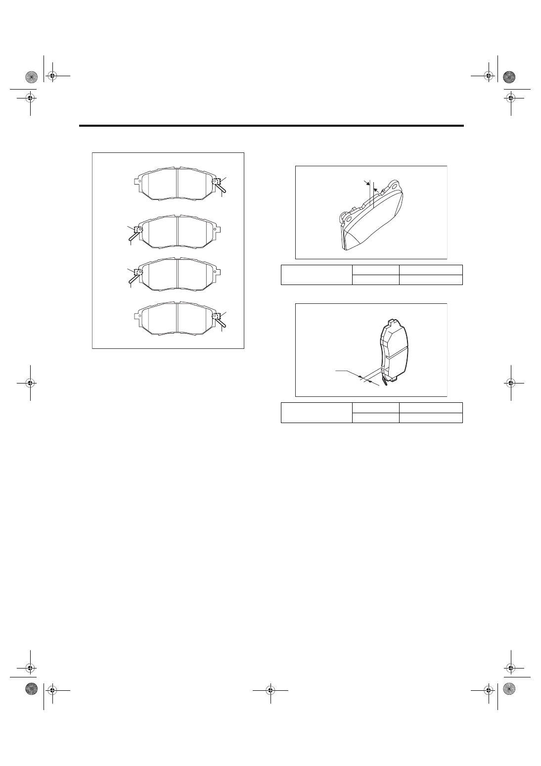
C: INSPECTION
Check the pad thickness A.
• Brembo type
• Except for brembo type
NOTE:
• Always replace the pads of both wheels and both
sides as a set.
• Replace the cross spring and pad pins if they are
twisted or worn. (Brembo type)
• A wear indicator is installed on the outer disc
brake pad. (Brembo type)
• Wear indicators are installed on the inner and
outer disc brake pads. (Except for brembo type)
• If the pad is worn to the limit, the end of wear in-
dicator contacts disc rotor, and a squeaking sound
is heard as the wheel rotates. If the sound is heard,
replace the pad.
• Replace the pad if there is oil or grease on it.
(1) LH — IN
(2) LH — OUT
(3) RH — IN
(4) RH — OUT
(5) Pad indicator
(6) Pad return spring
(1)
(2)
(3)
(4)
BR-00886
(6)
(5)
(6)
(5)
(6)
(5)
(6)
(5)
Pad thickness A
mm (in)
Standard
8.9 (0.35)
Wear limit
1.2 (0.047)
Pad thickness A
mm (in)
Standard
11 (0.433)
Wear limit
1.5 (0.059)
A
BR-00296
BR-00888
A
Нет комментариевНе стесняйтесь поделиться с нами вашим ценным мнением.
Текст