Subaru Impreza 3 / Impreza WRX / Impreza WRX STI. Service manual — part 558
BR-17
Front Disc Rotor
BRAKE
3. Front Disc Rotor
A: REMOVAL
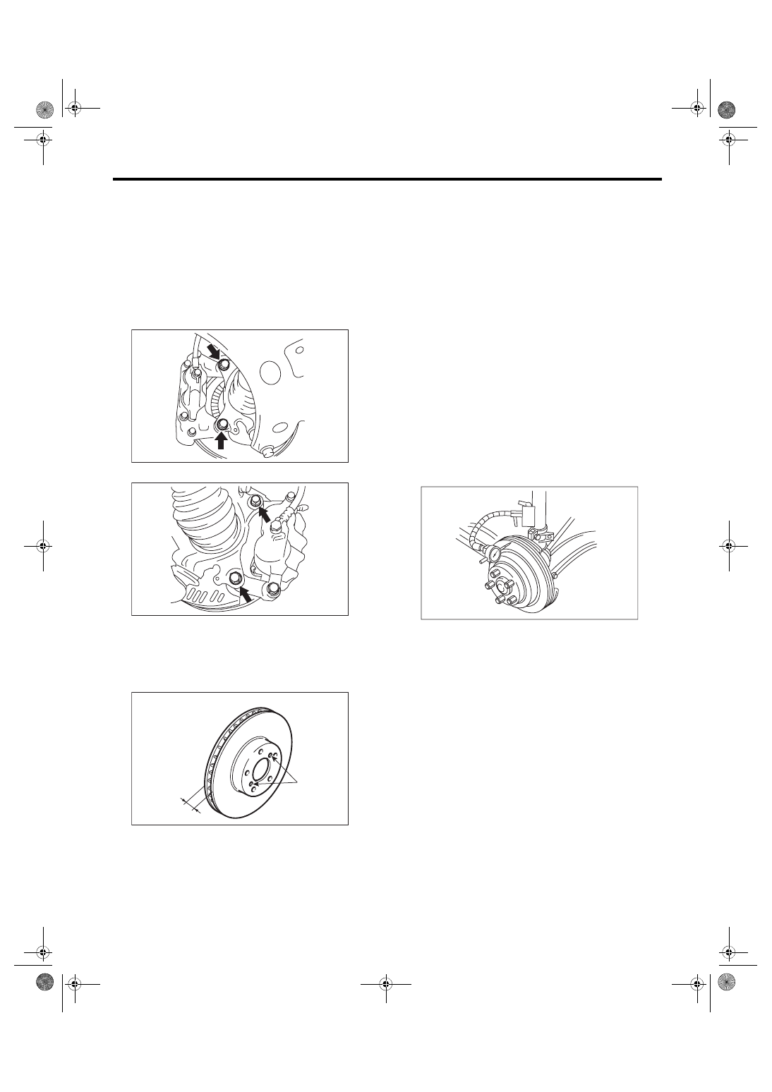
1) Lift up the vehicle, and then remove the front
wheels.
2) Remove the caliper body assembly from hous-
ing, and suspend it from the strut using a wire.
CAUTION:
Be careful not to stretch the brake hose.
• Brembo type
• Except for brembo type
3) Remove the disc rotor.
NOTE:
If it is difficult to remove the disc rotor from the hub,
drive an 8 mm bolt into the threaded section (B) of
the rotor, then remove the rotor.
4) Remove mud and foreign matter from the caliper
body assembly.
B: INSTALLATION
1) Install the disc rotor.
2) Install the caliper body assembly to the housing.
Tightening torque:
Brembo type
155 N·m (15.81 kgf-m, 114.3 ft-lb)
Except for brembo type
80 N·m (8.16 kgf-m, 59 ft-lb)
3) Install the front wheels.
C: INSPECTION
1) Check the front wheel bearing play and axle hub
runout before the inspection of disc rotor runout
limit. <Ref. to DS-17, INSPECTION, Front Axle.>
2) Secure the disc rotor by tightening the five wheel
nuts.
3) Set a dial gauge 10 mm (0.39 in) inward from the
disc rotor outer circumference. Rotate the disc rotor
to check runout. If the disc rotor runout exceeds the
limit, resurface the disc rotor. After grinding, check
the thickness of the disc rotor according to the pro-
cedure in step 4).
Disc rotor runout limit:
Brembo type
0.075 mm (0.0030 in)
Except for brembo type
0.050 mm (0.0020 in)
BR-00297
BR-00017
BR-00018
B
A
BR-00019
BR-18
Front Disc Rotor
BRAKE
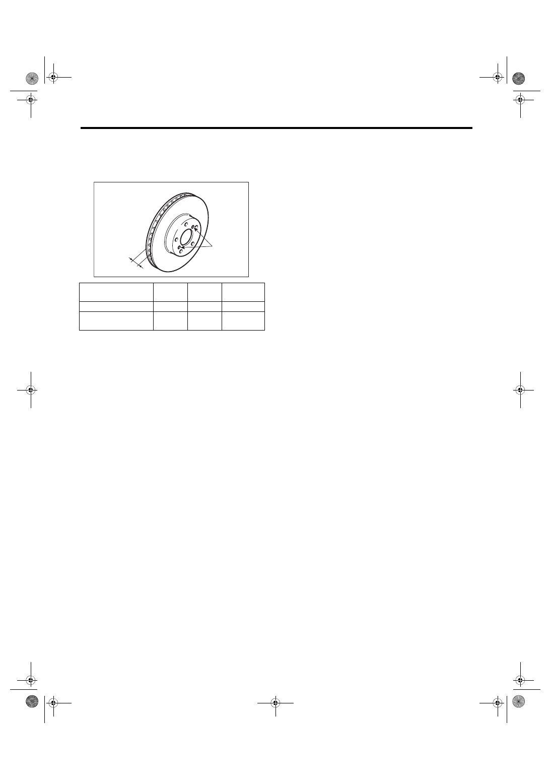
4) Set a micrometer 10 mm (0.39 in) inward from
the disc rotor outer perimeter, and then measure
the disc rotor thickness. If the thickness A of the
disc rotor exceeds the service limit, replace with a
new disc rotor.
Disc rotor thickness A
mm (in)
Standard
Limit
Disc rotor
diameter
Brembo type
30 (1.18) 28 (1.10) 326 (12.83)
Except for brembo
type
24 (0.94) 22 (0.87) 294 (11.57)
BR-00018
B
A
BR-19
Front Disc Brake Assembly
BRAKE
4. Front Disc Brake Assembly
A: REMOVAL
1. BREMBO TYPE
CAUTION:
Do not allow brake fluid to come in contact with
the painted surface of the vehicle body. If it
does, wash off with water immediately and wipe
away completely.
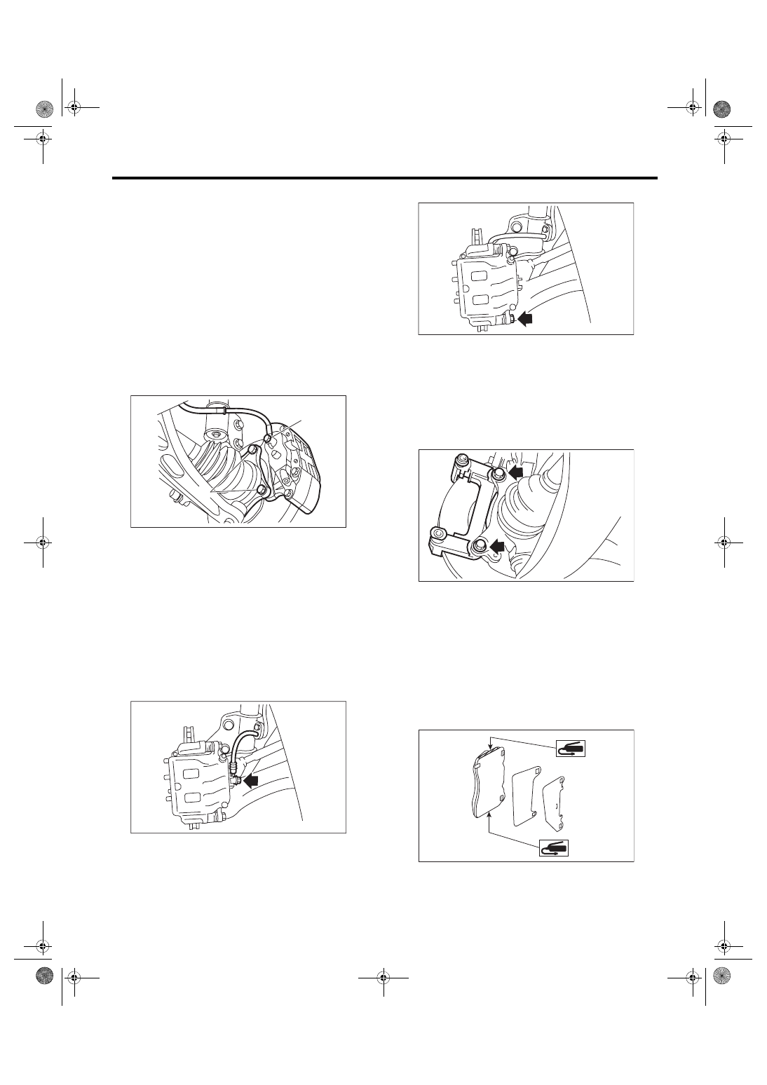
1) Lift up the vehicle, and then remove the front
wheels.
2) Remove the union bolt (1) and brake hose from
the caliper body.
3) Remove the mounting bolts (2) from the hous-
ing.
4) Remove mud and foreign matter from the caliper
body assembly.
2. EXCEPT FOR BREMBO TYPE
CAUTION:
Do not allow brake fluid to come in contact with
the painted surface of the vehicle body. If it
does, wash off with water and wipe away com-
pletely.
1) Lift up the vehicle, and then remove the front
wheels.
2) Remove the union bolt, and disconnect the
brake hose from the caliper body.
3) Remove the bolts which secure the caliper body.
4) Raise the caliper body, and then move it toward
vehicle center to separate it from the support.
5) Remove the brake pad, and then remove the
support from the housing.
NOTE:
Remove the support only when replacing the rotor
or support. It is not necessary to remove it when
servicing the caliper body.
6) Remove mud and foreign matter from the caliper
body and the support.
B: INSTALLATION
1. BREMBO TYPE
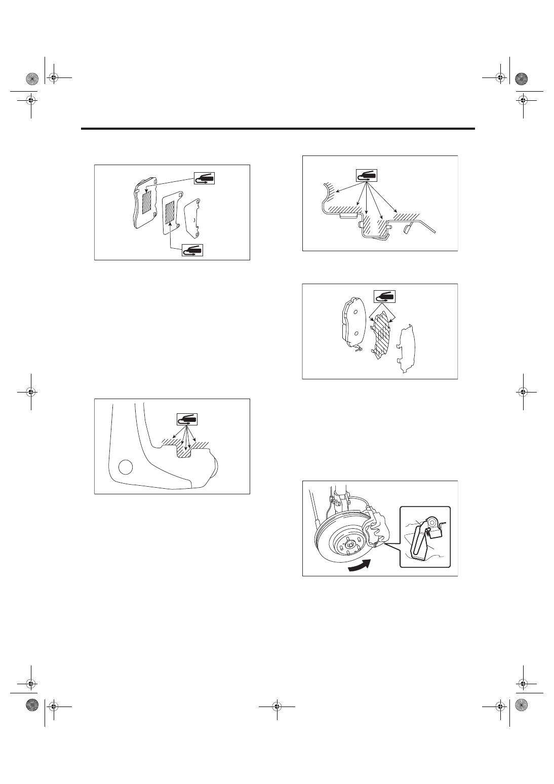
1) Install the caliper body assembly to the housing.
Tightening torque:
155 N·m (15.81 kgf-m, 114.3 ft-lb)
2) Apply a thin coat of Molykote M7439 or grease
contained in the pad kit to the pad side.
(1)
(2)
BR-00299
BR-00021
BR-00022
BR-00023
BR-00782
BR-20
Front Disc Brake Assembly
BRAKE
3) Apply a thin coat of Molykote AS880N (Part No.
K0777YA010) or grease contained in the pad kit to
the pad and pad shim.
4) Install the pads to the caliper body.
5) Install the cross spring.
6) Install the pad pins.
7) Install the clips.
8) Connect the brake hose using a new brake hose
gasket.
Tightening torque:
18 N·m (1.84 kgf-m, 13.3 ft-lb)
9) Bleed air from the brake system. <Ref. to BR-41,
2. EXCEPT FOR BREMBO TYPE
1) Apply a thin coat of Molykote M7439 or grease
contained in the pad kit to the support.
2) Install the support to the housing.
Tightening torque:
80 N·m (8.16 kgf-m, 59 ft-lb)
3) Apply a thin coat of Molykote M7439 or grease
contained in the pad kit to the pad clip.
4) Apply a thin coat of Molykote AS880N (Part No.
K0777YA010) or grease contained in the pad kit to
both surfaces of the pad and inner shim.
5) Install the pad to support.
CAUTION:
• Be sure to install so that the pad return
spring faces the input side of the direction of
brake rotor rotation, as shown in the figure.
• Correctly install the pad return spring to the
supporting surface of the pad clip as shown in
the figure.
• If the pad return spring is deformed or dam-
aged, replace the brake pad.
BR-00783
BR-00597
(1) Pad return spring
(2) Supporting surface of pad clip
(3) Direction of brake rotor rotation
BR-00596
BR-00837
BR-00885
(3)
(1)
(2)
Нет комментариевНе стесняйтесь поделиться с нами вашим ценным мнением.
Текст