Subaru Impreza 3 / Impreza WRX / Impreza WRX STI. Service manual — part 503
DI-57
Rear Differential Front Member
DIFFERENTIALS
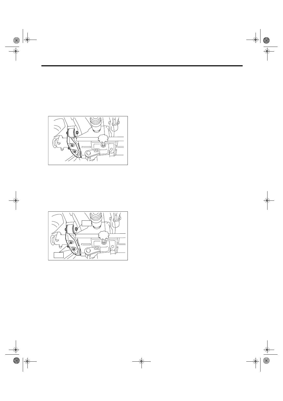
7. Rear Differential Front Mem-
ber
A: REMOVAL
1) Disconnect the ground cable from battery.
2) Lift up the vehicle.
3) Support the rear differential using transmission
jack, and then remove the rear differential front
member.
B: INSTALLATION
Install the rear differential front member with a new
self-locking nut.
Tightening torque:
T1: 50 N·m (5.1 kgf-m, 36.9 ft-lb)
T2: 110 N·m (11.2 kgf-m, 81.1 ft-lb)
C: INSPECTION
1) Check the rear differential front member for
damage, bend and corrosion.
If damage, bend or corrosion is excessive, replace
the rear differential front member.
2) Check the bushings of rear differential front
member for cracking, hardening and damage.
If cracking, hardening or damage is excessive, re-
place rear differential front member.
(A) Rear differential front member
DI-00540
(A)
DI-00541
T2
T1
DI-58
Rear Differential Mount Bushing
DIFFERENTIALS
8. Rear Differential Mount Bush-
ing
A: INSPECTION
Check the rear differential mounting bushing for
cracks, hardening, or damage. If cracking, harden-
ing, or damage is excessive, replace the rear differ-
ential mounting bushing.
B: REPLACEMENT
CAUTION:
• If there was so much rust in the rear differen-
tial mount bushing, remove the rust before
starting work.
• Apply the molybdenum grease on the square
thread of the ST (shaft and nut) before use.
1) Remove the rear differential. <Ref. to DI-22, RE-
MOVAL, Rear Differential (T-type).>
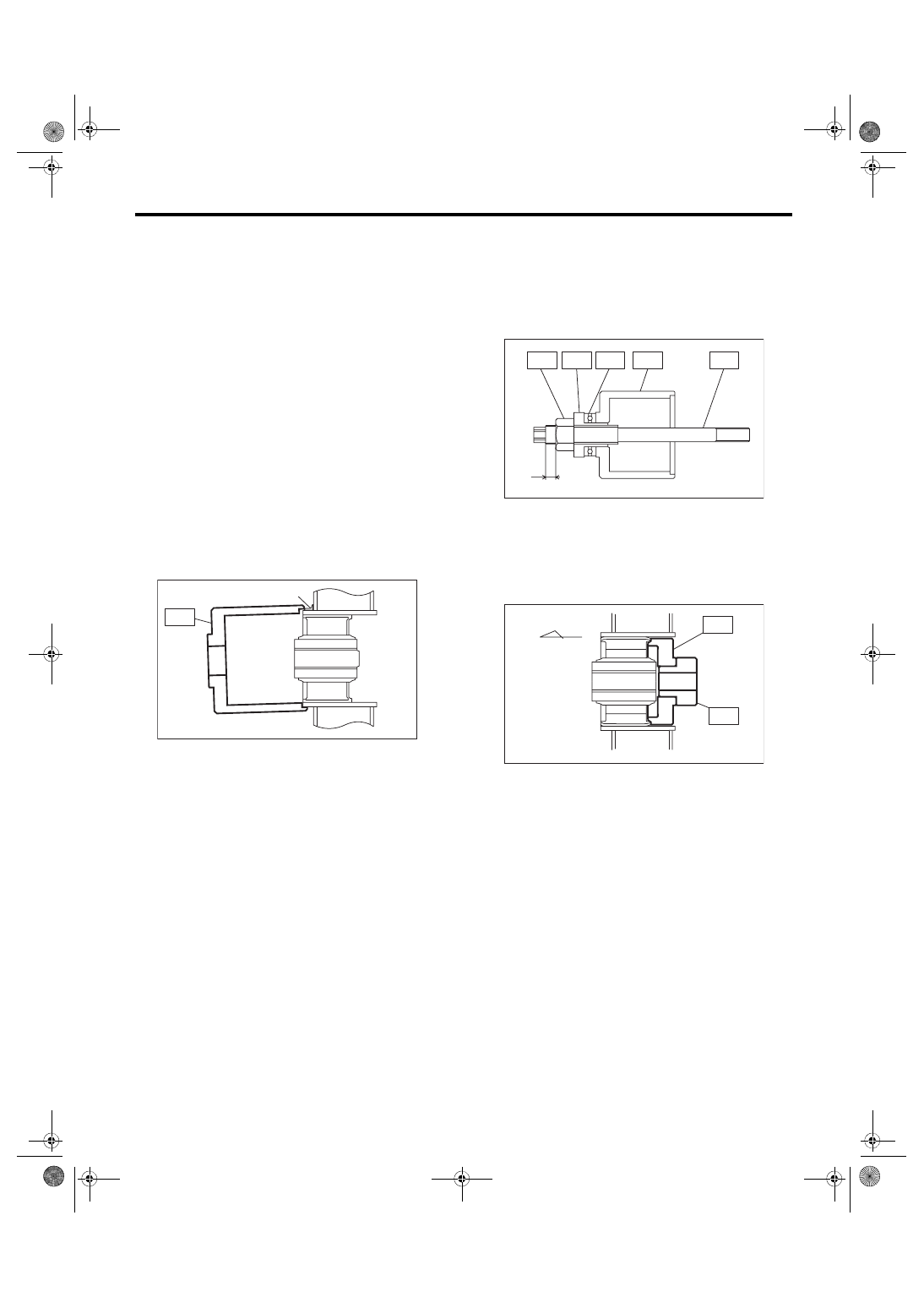
2) Fit the ST to the periphery of the sub frame cyl-
inder, and make sure that the ST does not contact
with welded spots or spatters.
ST 41399FG010 SPECIAL TOOL A
3) If the ST contacts with welded spots or spatters,
remove the excessive welds or spatters with sand-
er or the equivalent so that the ST contacts the cyl-
inder peripheral part.
CAUTION:
Performing the operation with the ST contact-
ing with welded spots or spatters may break the
ST. Be sure to remove excessive welds or spat-
ters before the operation.
4) Set ST1, ST2, ST3, ST4 and ST5 as shown in
the figure.
ST1 41399FG091 SPECIAL TOOL SHAFT
ST2 41399FG070 SPECIAL TOOL NUT
ST3 41399FG050 SPECIAL TOOL SLEEVE
ST4 41399FG080 SPECIAL TOOL BEARING
ST5 41399FG010 SPECIAL TOOL A
5) Fit and hold the ST1 and ST2 to the rear differ-
ential mount bushing from the rear side of vehicle.
ST1 41399FG031 SPECIAL TOOL C
ST2 41399FG061 SPECIAL TOOL RING
(A) Welded spot
DI-00655
ST
(A)
(A) 5 mm (0.2 in) or less
(A) Front side of vehicle
DI-00656
ST4
(A)
ST1
ST2
ST3
ST5
DI-00657
(A)
ST2
ST1
DI-59
Rear Differential Mount Bushing
DIFFERENTIALS
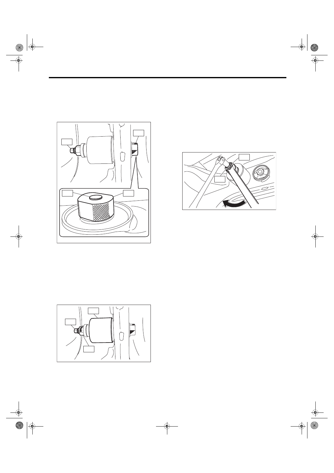
6) Insert the ST set in the step 4) through the rear
differential mount bushing hole from the front side
of vehicle, and screw in the ST1 by hand till the
front end of ST1 comes out slightly from the rear
end of ST2.
ST1 41399FG091 SPECIAL TOOL SHAFT
ST2 41399FG061 SPECIAL TOOL RING
7) Hold the ST1 to prevent it from rotating, and
screw in the ST3 by hand till there is no loose fit on
the ST2.
CAUTION:
When setting the ST to the vehicle, always
make sure that the ST2 fits the periphery of the
sub frame cylinder and is not tilted.
ST1 41399FG091 SPECIAL TOOL SHAFT
ST2 41399FG010 SPECIAL TOOL A
ST3 41399FG070 SPECIAL TOOL NUT
8) Hold the ST1 with a tool to prevent it from rotat-
ing, and screw in the ST2 to remove the rear differ-
ential mount bushing.
CAUTION:
• Rotation of ST1 will damage the screw at the
rear end of rear differential mount bushing.
Never rotate the ST1.
• If the ST starts to tilt while removing the rear
differential mount bushing, stop the work and
set the ST again.
ST1 41399FG091 SPECIAL TOOL SHAFT
ST2 41399FG070 SPECIAL TOOL NUT
DI-00708
ST1
ST1
ST2
ST2
DI-00659
ST1
ST3
ST2
DI-00660
ST2
ST1
DI-60
Rear Differential Mount Bushing
DIFFERENTIALS
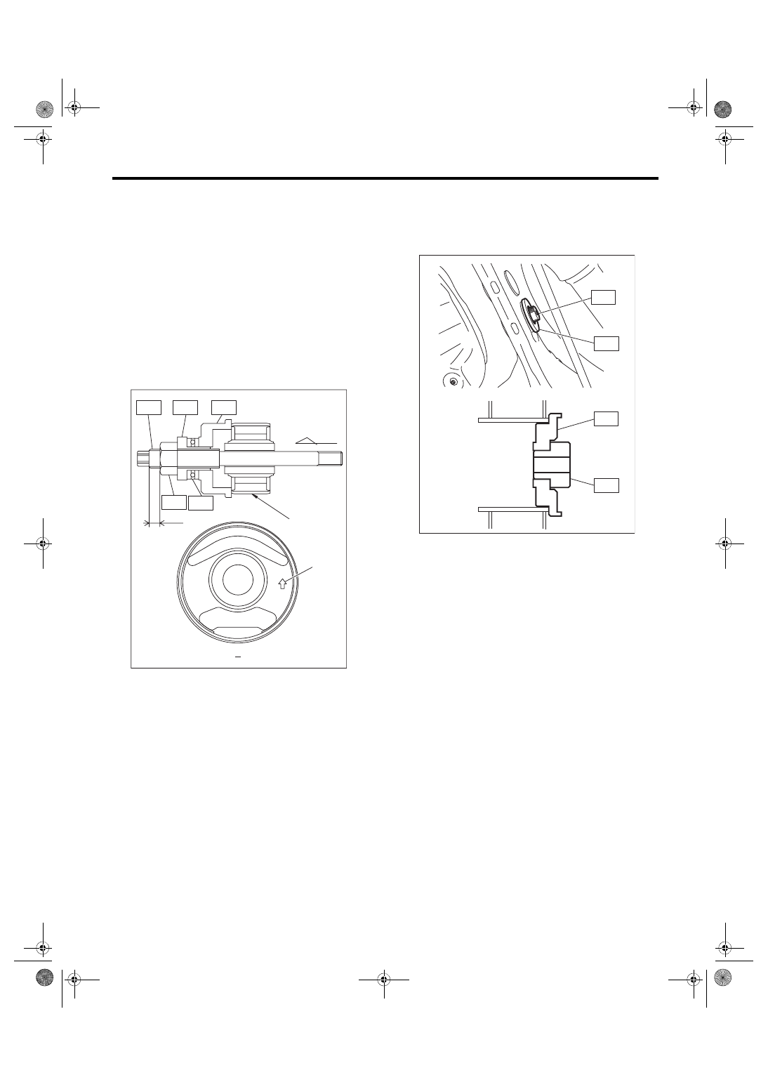
9) Set ST1, ST2, ST3, ST4, ST5 and rear differen-
tial mount bushing as shown in the figure.
NOTE:
• Set the ST2 nut near to the end of ST1 screw.
• Hold the rear differential mount bushing with the
arrow marked side facing toward the rear of the ve-
hicle, and set the rear differential mount bushing to
the ST so that the arrow mark faces upward.
• Mark the bottom end of rear differential mount
bushing to identify the installing direction.
ST1 41399FG091 SPECIAL TOOL SHAFT
ST2 41399FG070 SPECIAL TOOL NUT
ST3 41399FG050 SPECIAL TOOL SLEEVE
ST4 41399FG080 SPECIAL TOOL BEARING
ST5 41399FG020 SPECIAL TOOL B
10) Attach ST1 to the ST2, and fit and hold the STs
as a unit to the sub frame from the rear side of ve-
hicle.
ST1 41399FG061 SPECIAL TOOL RING
ST2 41399FG041 SPECIAL TOOL D
(A) 8 mm (0.31 in) or more
(B) Arrow mark
(C) Marked position
DI-00982
UP
Z
(B)
(C)
Z
ST1
ST2
ST3
ST4
ST5
(A)
DI-00662
ST1
ST2
ST2
ST1
Нет комментариевНе стесняйтесь поделиться с нами вашим ценным мнением.
Текст