Subaru Impreza 3 / Impreza WRX / Impreza WRX STI. Service manual — part 138
FU(w/o STI)-79
Fuel Pump
FUEL INJECTION (FUEL SYSTEMS)
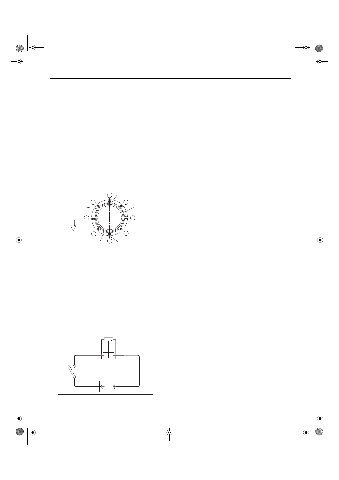
B: INSTALLATION
Install in the reverse order of removal while being
careful of the following.
• Make sure the sealing portion is free from fuel or
foreign matter before installation.
• Align protrusion (A) of the gasket to the position
shown in the figure.
• Insert the protrusion (B) of gasket to the fuel
pump upper plate. (3 places)
• Align the protrusion (C) of fuel pump assembly
with the cutout on the fuel pump upper plate.
• Tighten the nuts to the specified torque in the or-
der as shown in the figure.
NOTE:
Use a new gasket.
Tightening torque:
4.4 N·m (0.4 kgf-m, 3.2 ft-lb)
C: INSPECTION
1) Check that the fuel pump has no deformation,
cracks or other damages.
2) Connect the battery positive terminal to terminal
No. 5 and the battery ground terminal to terminal
No. 6, and inspect the fuel pump operation.
WARNING:
• Wipe off fuel completely.
• Keep the battery as far apart from fuel pump
as possible.
• Do not run the fuel pump for a long time un-
der non-load condition.
(a) Front side of vehicle
FU-04532
1
2
3
4
5
6
7
8
(C)
(B)
(B)
(B)
(A)
(a)
FU-04110
2 1
4 3
6 5
FU(w/o STI)-80
Fuel Level Sensor
FUEL INJECTION (FUEL SYSTEMS)
27.Fuel Level Sensor
A: REMOVAL
WARNING:
Place “NO OPEN FLAMES” signs near the
working area.
CAUTION:
• Be careful not to spill fuel.
• If the fuel gauge indicates that two thirds or
more of the fuel is remaining, be sure to drain
fuel before starting work to avoid the fuel to
spill.
NOTE:
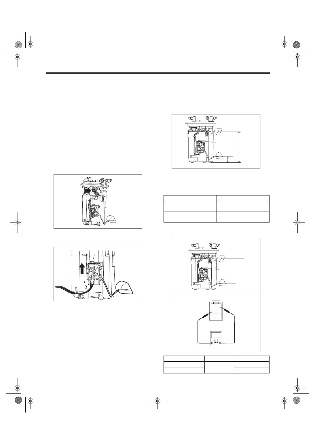
The fuel level sensor is built in fuel pump assembly.
1) Remove the fuel pump assembly. <Ref. to FU(w/
o STI)-78, REMOVAL, Fuel Pump.>
2) Disconnect the fuel level sensor connector.
3) Slide the fuel level sensor in the direction of the
arrow and remove the fuel level sensor by pressing
the claw (A) of the fuel level sensor.
B: INSTALLATION
Install in the reverse order of removal.
C: INSPECTION
1) Check that the fuel level sensor has no damage.
2) Measure the fuel level sensor float position.
NOTE:
When inspecting the fuel level sensor, perform the
work with the sensor installed to the fuel pump.
3) Measure the resistance between fuel level sen-
sor terminals.
FU-04223
FU-04224
(A)
(1) FULL
(2) EMPTY
(3) Fuel tank seating surface
Float position
Standard
FULL to Fuel tank seating
surface (A)
135±4 mm (5.315±0.157 in)
EMPTY to Fuel tank seating
surface (B)
23.7±4 mm (0.933±0.157 in)
Float position
Terminal No.
Standard
FULL (A)
1 and 4
2.0±1.0 Ω
EMPTY (B)
31.9±1.0 Ω
FU-04229
(1)
(A)
(3)
(B)
(2)
FU-04230
2 1
4 3
6 5
(B)
(A)
FU(w/o STI)-81
Fuel Sub Level Sensor
FUEL INJECTION (FUEL SYSTEMS)
28.Fuel Sub Level Sensor
A: REMOVAL
WARNING:
Place “NO OPEN FLAMES” signs near the
working area.
CAUTION:
• Be careful not to spill fuel.
• Catch the fuel from the tubes using a contain-
er or cloth.
• If the fuel gauge indicates that two thirds or
more of the fuel is remaining, be sure to drain
fuel before starting work to avoid the fuel to
spill.
1) Release the fuel pressure. <Ref. to FU(w/o STI)-
65, RELEASING OF FUEL PRESSURE, PROCE-
2) Drain fuel. <Ref. to FU(w/o STI)-65, DRAINING
FUEL (WITH SUBARU SELECT MONITOR),
3) Disconnect the ground cable from battery.
4) Remove the rear seat cushion. <Ref. to SE-13,
5) Remove the service hole cover.
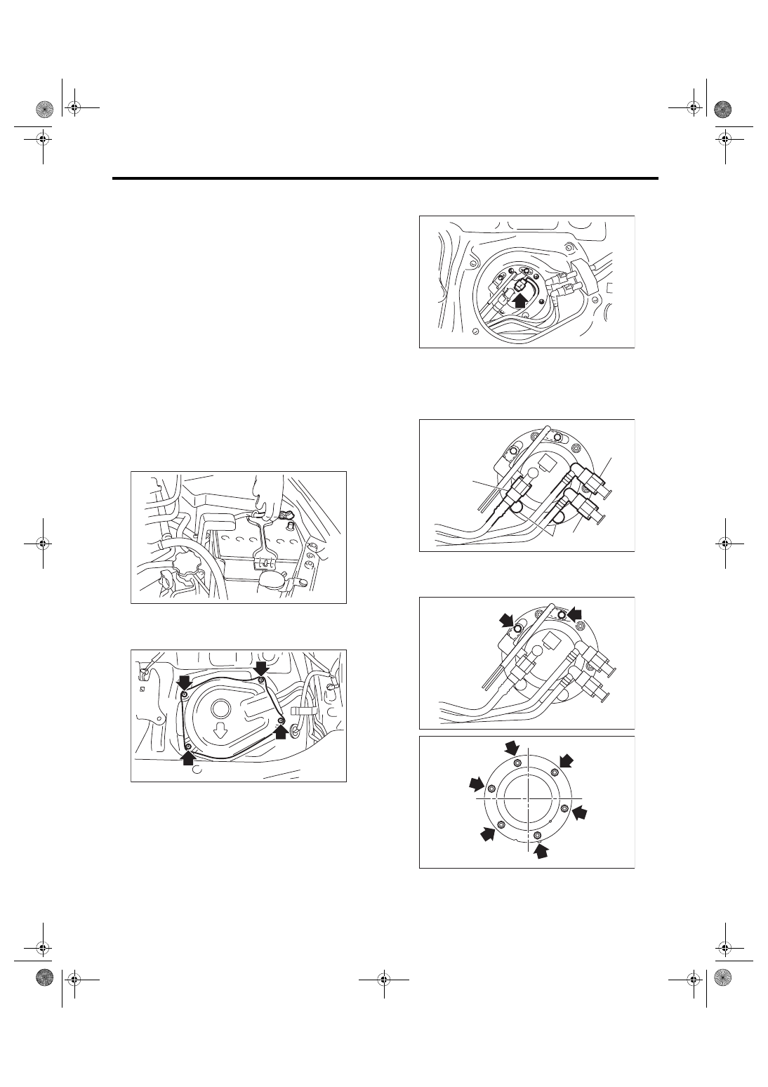
6) Disconnect the connector from the fuel sub level
sensor.
7) Disconnect the quick connectors of fuel delivery
tube (A), fuel return tube (B), and jet pump tube (C).
<Ref. to FU(w/o STI)-89, REMOVAL, Fuel Deliv-
ery, Return and Evaporation Lines.>
8) Remove the rubber cap (D) from the nut.
9) Remove the bolts and nuts which hold fuel sub
level sensor protector and fuel sub level sensor up-
per plate to the fuel tank.
10) Remove the fuel sub level sensor from the fuel
tank.
IN-00203
FU-06553
FU-03364
FU-04239
(A)
(B)
(C)
(D)
FU-01146
FU-04569
FU(w/o STI)-82
Fuel Sub Level Sensor
FUEL INJECTION (FUEL SYSTEMS)
B: INSTALLATION
Install in the reverse order of removal while being
careful of the following.
• Make sure the sealing portion is free from fuel or
foreign matter before installation.
• Align protrusion (A) of the gasket to the position
shown in the figure.
• Align protrusion (B) of the fuel sub level sensor to
the cutout in the fuel sub level sensor upper plate.
• Tighten the nuts and bolts to the specified torque
in the order as shown in the figure.
• After tightening, install the rubber cap (C) at the
position shown in the figure.
NOTE:
• Use a new gasket.
• Do not forget to install rubber cap (C).
Tightening torque:
4.4 N·m (0.4 kgf-m, 3.2 ft-lb)
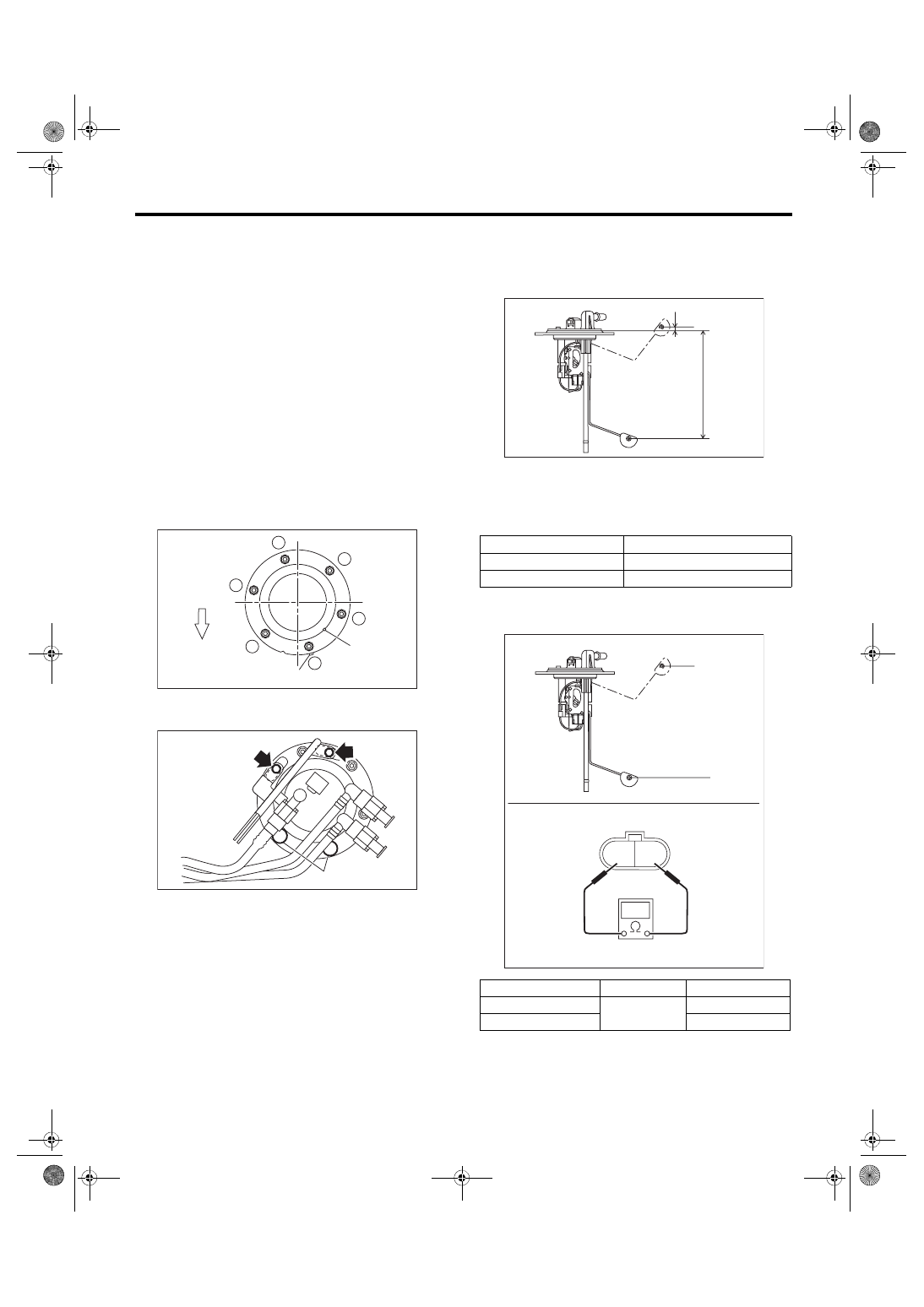
C: INSPECTION
1) Check that the fuel sub level sensor has no dam-
age.
2) Measure the fuel sub level sensor float position.
3) Measure the resistance between fuel sub level
sensor terminals.
(a) Front side of vehicle
FU-04533
1
6
5
2
4
3
(B)
(A)
(a)
FU-04242
(C)
(1) FULL
(2) EMPTY
(3) Datum points
Float position
Standard
FULL to Datum point (A)
5.31±3.5 mm (0.209±0.138 in)
EMPTY to Datum point (B) 160.6±3.5 mm (6.323±0.138 in)
Float position
Terminal No.
Standard
FULL (A)
1 and 2
2.0
+0.5
–1.0
Ω
EMPTY (B)
62.1±1.0 Ω
(1)
(B)
(2)
(A)
FU-04213
(3)
FU-04214
2 1
(B)
(A)
Нет комментариевНе стесняйтесь поделиться с нами вашим ценным мнением.
Текст