Subaru Impreza 3 / Impreza WRX / Impreza WRX STI. Service manual — part 139
FU(w/o STI)-83
Fuel Filter
FUEL INJECTION (FUEL SYSTEMS)
29.Fuel Filter
A: REMOVAL
WARNING:
Place “NO OPEN FLAMES” signs near the
working area.
CAUTION:
• Be careful not to spill fuel.
• If the fuel gauge indicates that two thirds or
more of the fuel is remaining, be sure to drain
fuel before starting work to avoid the fuel to
spill.
• Be careful not to drop or apply any impact to
the fuel pump during work. This may deterio-
rate its performance.
NOTE:
The fuel filter is built in fuel pump assembly.
1) Remove the fuel pump assembly. <Ref. to FU(w/
o STI)-78, REMOVAL, Fuel Pump.>
2) Remove the fuel level sensor. <Ref. to FU(w/o
STI)-80, REMOVAL, Fuel Level Sensor.>
3) Disconnect the pump assembly connector from
sub tank bracket assembly.
4) Cut off the tab holders connecting the sub tank
bracket assembly and the sub tank in four loca-
tions, and separate the sub tank bracket assembly
and the sub tank.
CAUTION:
Be careful not to damage the sub tank.
NOTE:
If the O-ring is remaining on the sub tank, remove.
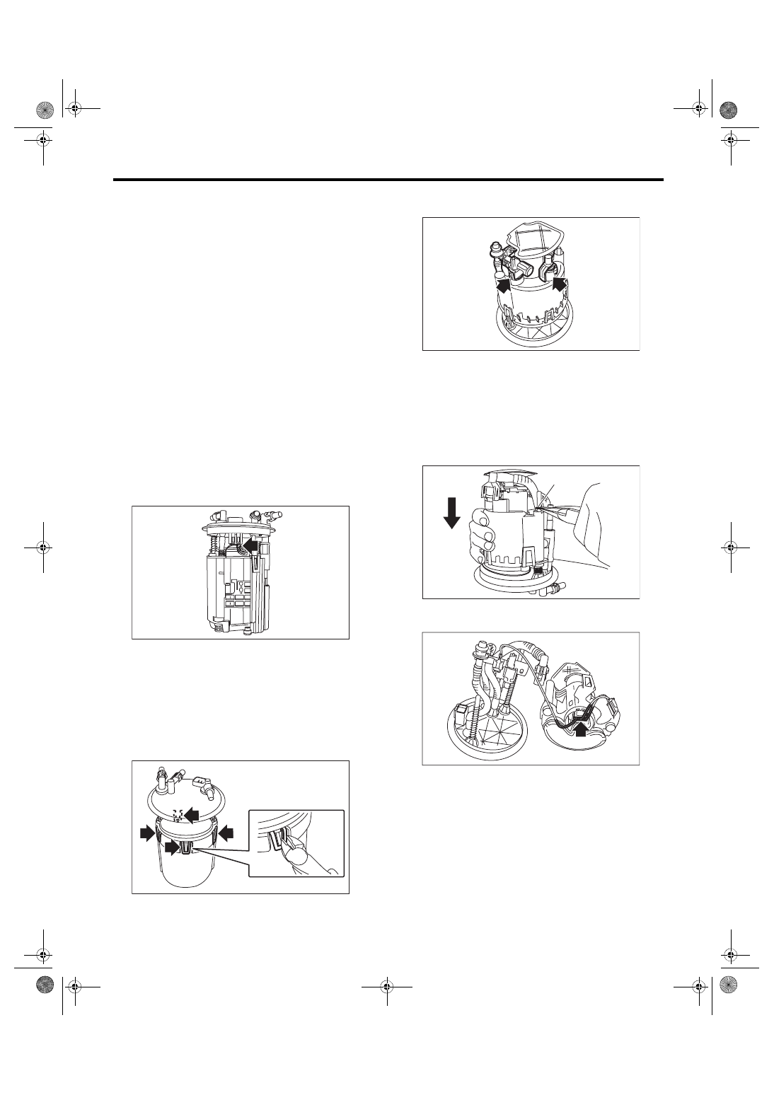
5) Disconnect two connectors of fuel delivery pipe
from fuel filter assembly.
6) Push to compress the fuel filter assembly in the
direction of the arrow, remove clip (A), and sepa-
rate the sub tank bracket assembly and the fuel fil-
ter assembly.
CAUTION:
When separating the sub tank bracket assem-
bly and the fuel filter assembly, be careful not
to damage the ground wire.
7) Disconnect the connector from the pump assem-
bly.
FU-03849
FU-03850
FU-05678
FU-03852
(A)
FU-03853
FU(w/o STI)-84
Fuel Filter
FUEL INJECTION (FUEL SYSTEMS)
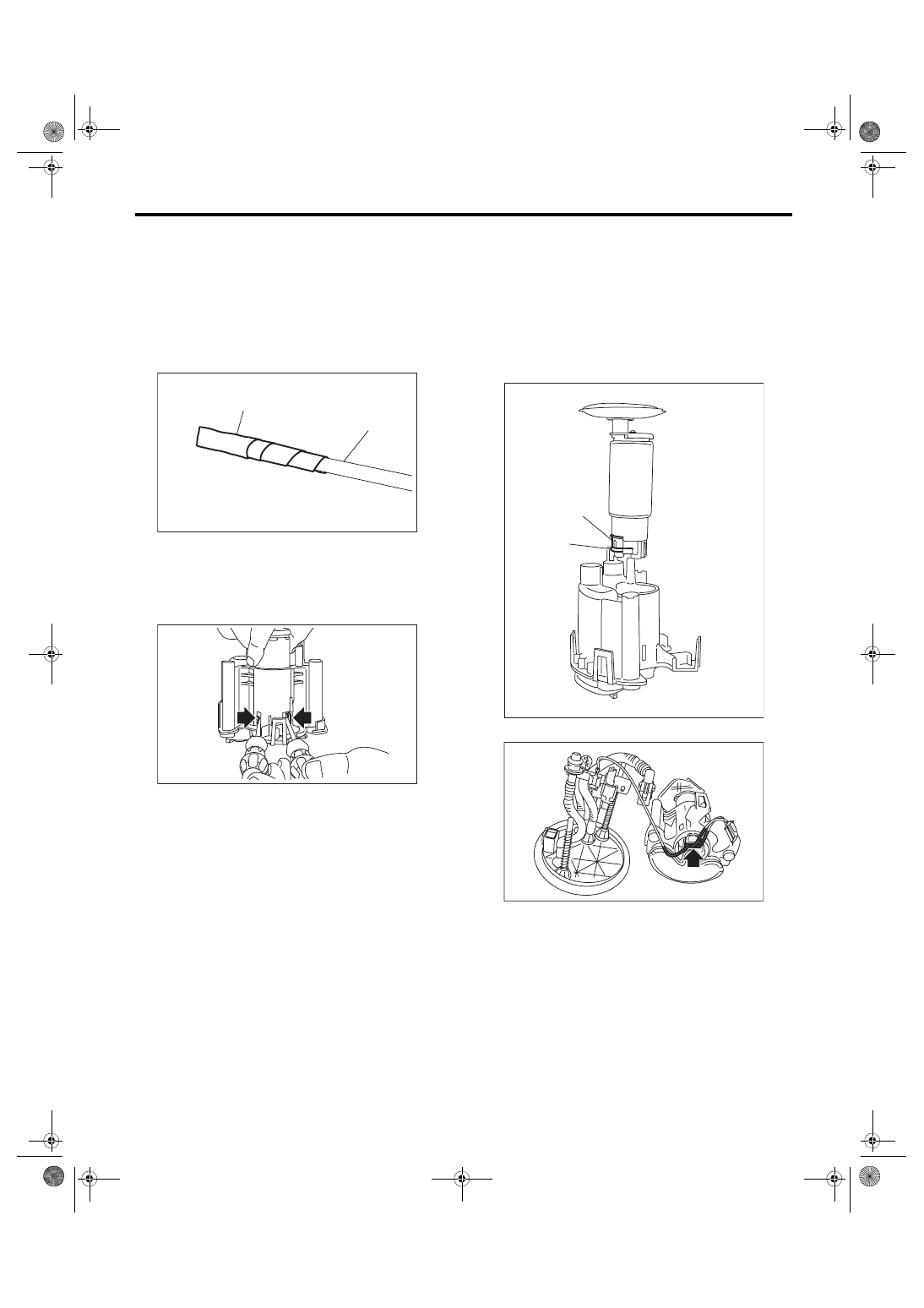
8) Lift the two tab holders connecting the pump as-
sembly to the fuel filter using a flat tip screwdriver
(with a shaft diameter of approx. 3 mm (0.12 in)),
etc., and separate the fuel filter and pump assem-
bly.
CAUTION:
• To prevent damaging the tabs of the pump
assembly, wrap the tip of flat tip screwdriver
(A), etc. with tape (B).
• Be careful not to drop or apply any impact to
the pump assembly.
NOTE:
If the spacer and O-ring are remaining on the pump
assembly, remove them.
B: INSTALLATION
1) Assemble O-ring (A) and spacer (B) to the pump
assembly and attach the pump assembly to the fuel
filter.
NOTE:
• Use new O-rings (8 mm (0.31 in) inner diameter).
• Use a new spacer.
• Apply gasoline to the O-ring.
• Insert the pump assembly until a click is heard.
2) Connect the connector to the pump assembly.
FU-03929
(B)
(A)
FU-03927
(A)
(B)
FU-03859
FU-03853
FU(w/o STI)-85
Fuel Filter
FUEL INJECTION (FUEL SYSTEMS)
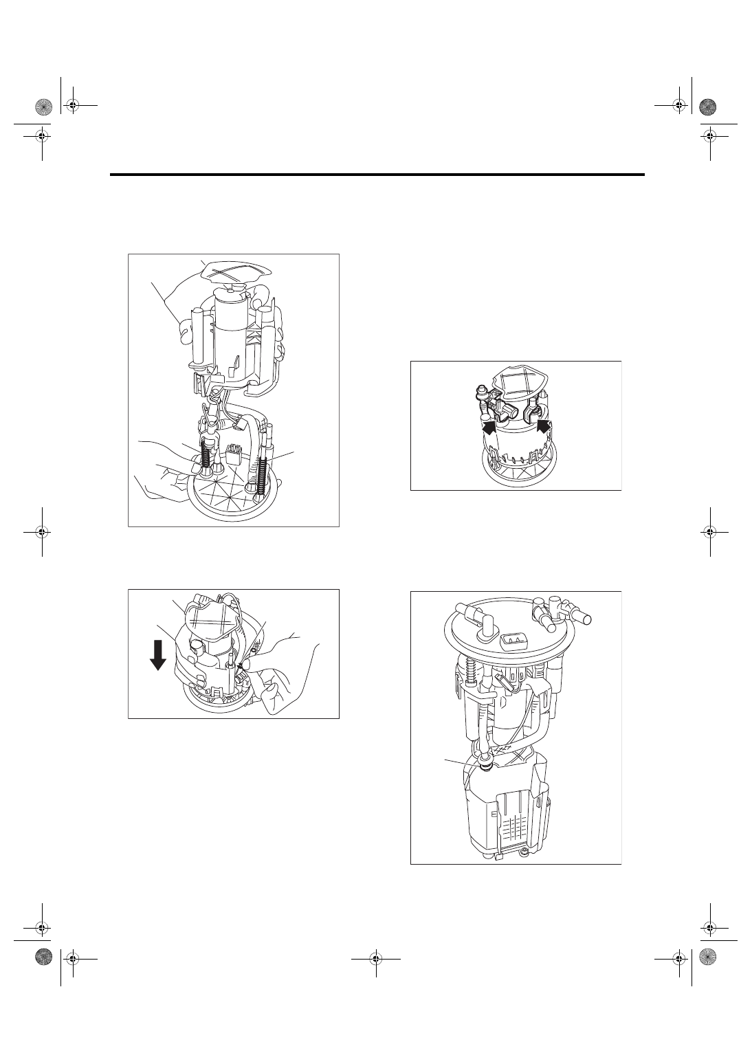
3) Attach spring (A) to the metal rod of the sub tank
bracket assembly, and assemble the fuel filter as-
sembly.
NOTE:
Use a new spring.
4) Push the fuel filter assembly in the direction of
the arrow to compress, and attach clip (A).
NOTE:
Use a new clip.
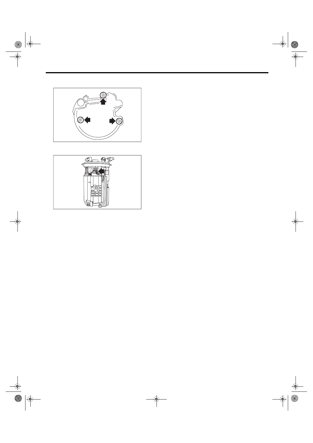
5) Connect the fuel piping connector to the fuel fil-
ter assembly.
NOTE:
• Use new O-rings.
• Apply gasoline to the O-ring.
• The O-rings of the black and white connectors
are identified by a difference in diameter. Be careful
not to confuse the two during assembly.
O-ring inner diameter:
Black connector O-ring [Approx. 7 mm (0.28
in)]
White connector O-ring [Approx. 8 mm (0.31
in)]
6) Attach the O-ring (A) to the fuel filter assembly,
and attach the sub tank to the sub tank bracket as-
sembly.
NOTE:
• Use new O-rings (8 mm (0.31 in) inner diameter).
• Apply gasoline to the O-ring.
• Insert the pump assembly until a “pop” is heard.
FU-03860
(A)
(A)
FU-03861
(A)
FU-05678
FU-03862
(A)
FU(w/o STI)-86
Fuel Filter
FUEL INJECTION (FUEL SYSTEMS)
7) Replace the cushion on the rear face of the sub
tank with a new cushion.
8) Connect the pump assembly connector to the
sub tank bracket assembly.
9) Install the fuel level sensor. <Ref. to FU(w/o
STI)-80, INSTALLATION, Fuel Level Sensor.>
10) Inspect the fuel level sensor. <Ref. to FU(w/o
STI)-80, INSPECTION, Fuel Level Sensor.>
11) Install the fuel pump assembly. <Ref. to FU(w/
o STI)-79, INSTALLATION, Fuel Pump.>
FU-03863
FU-03849
Нет комментариевНе стесняйтесь поделиться с нами вашим ценным мнением.
Текст