Subaru Impreza 3 / Impreza WRX / Impreza WRX STI. Service manual — part 34
FU(STI)-48
Tumble Generator Valve Assembly
FUEL INJECTION (FUEL SYSTEMS)
12.Tumble Generator Valve As-
sembly
A: REMOVAL
1) Release the fuel pressure. <Ref. to FU(STI)-67,
RELEASING OF FUEL PRESSURE, PROCE-
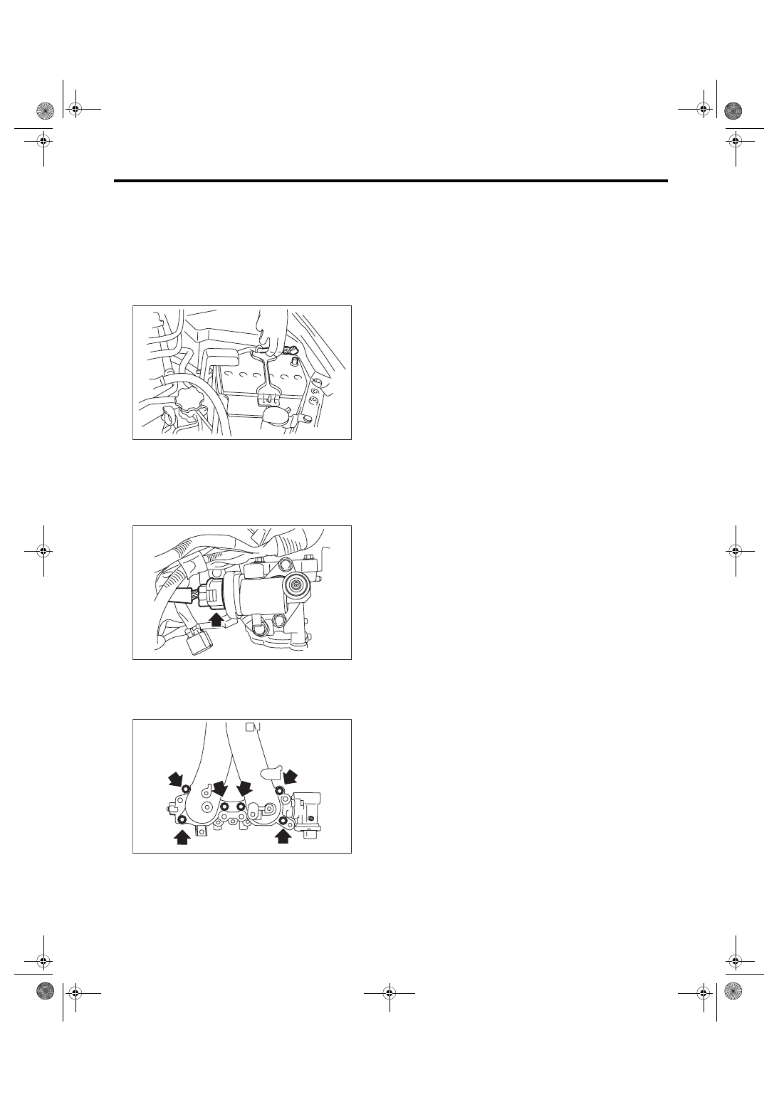
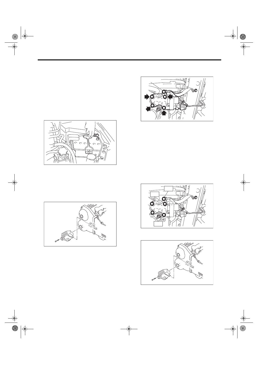
2) Disconnect the ground cable from battery.
3) Open the fuel filler lid and remove the fuel filler
cap.
4) Remove the intake manifold. <Ref. to FU(STI)-
17, REMOVAL, Intake Manifold.>
5) Disconnect the connector from the tumble gen-
erator valve assembly.
6) Remove the fuel injector. <Ref. to FU(STI)-45,
7) Remove the tumble generator valve assembly
from the intake manifold.
B: INSTALLATION
Install in the reverse order of removal.
NOTE:
Use a new gasket.
Tightening torque:
8.3 N·m (0.8 kgf-m, 6.1 ft-lb)
C: INSPECTION
1) Check that the tumble generator valve assembly
has no deformation, cracks or other damages.
2) Check tumble generator valve for contamination
or clogging.
IN-00203
FU-04604
FU-03603
FU(STI)-49
Tumble Generator Valve Actuator
FUEL INJECTION (FUEL SYSTEMS)
13.Tumble Generator Valve Ac-
tuator
A: SPECIFICATION
The tumble generator valve assembly cannot be
disassembled.
Refer to “Tumble Generator Valve Assembly” for
removal and installation procedures. <Ref. to
FU(STI)-48, REMOVAL, Tumble Generator Valve
FU(STI)-50
Oil Flow Control Solenoid Valve
FUEL INJECTION (FUEL SYSTEMS)
14.Oil Flow Control Solenoid
Valve
A: REMOVAL
1. INTAKE SIDE
Oil flow control solenoid valve is a unit with front
camshaft cap.
Refer to “Camshaft” for removal procedures. <Ref.
to ME(STI)-61, REMOVAL, Camshaft.>
2. EXHAUST SIDE
1) Disconnect the ground cable from battery.
2) Lift up the vehicle.
3) Remove the under cover. <Ref. to EI-28, RE-
4) Remove the front exhaust pipe. (right side only.)
<Ref. to EX(STI)-6, REMOVAL, Front Exhaust
5) Remove the engine harness cover. (right side
only.)
6) Disconnect the ground cable (A). (left side only)
7) Disconnect the connector (B) from the oil flow
control solenoid valve, and remove the oil flow con-
trol solenoid valve from the cylinder head.
B: INSTALLATION
1. INTAKE SIDE
Refer to “Camshaft” for installation procedure.
<Ref. to ME(STI)-64, INSTALLATION, Camshaft.>
2. EXHAUST SIDE
Install in the reverse order of removal.
NOTE:
Use a new gasket.
Tightening torque:
T1: 7.5 N·m (0.8 kgf-m, 5.5 ft-lb)
T2: 10 N·m (1.0 kgf-m, 7.4 ft-lb)
Tightening torque:
5 N·m (0.5 kgf-m, 3.7 ft-lb)
IN-00203
FU-03616
FU-05832
(A)
(B)
FU-03605
T1
T2
T2
FU-03616
FU(STI)-51
Oil Flow Control Solenoid Valve
FUEL INJECTION (FUEL SYSTEMS)
C: DISASSEMBLY
1. INTAKE SIDE
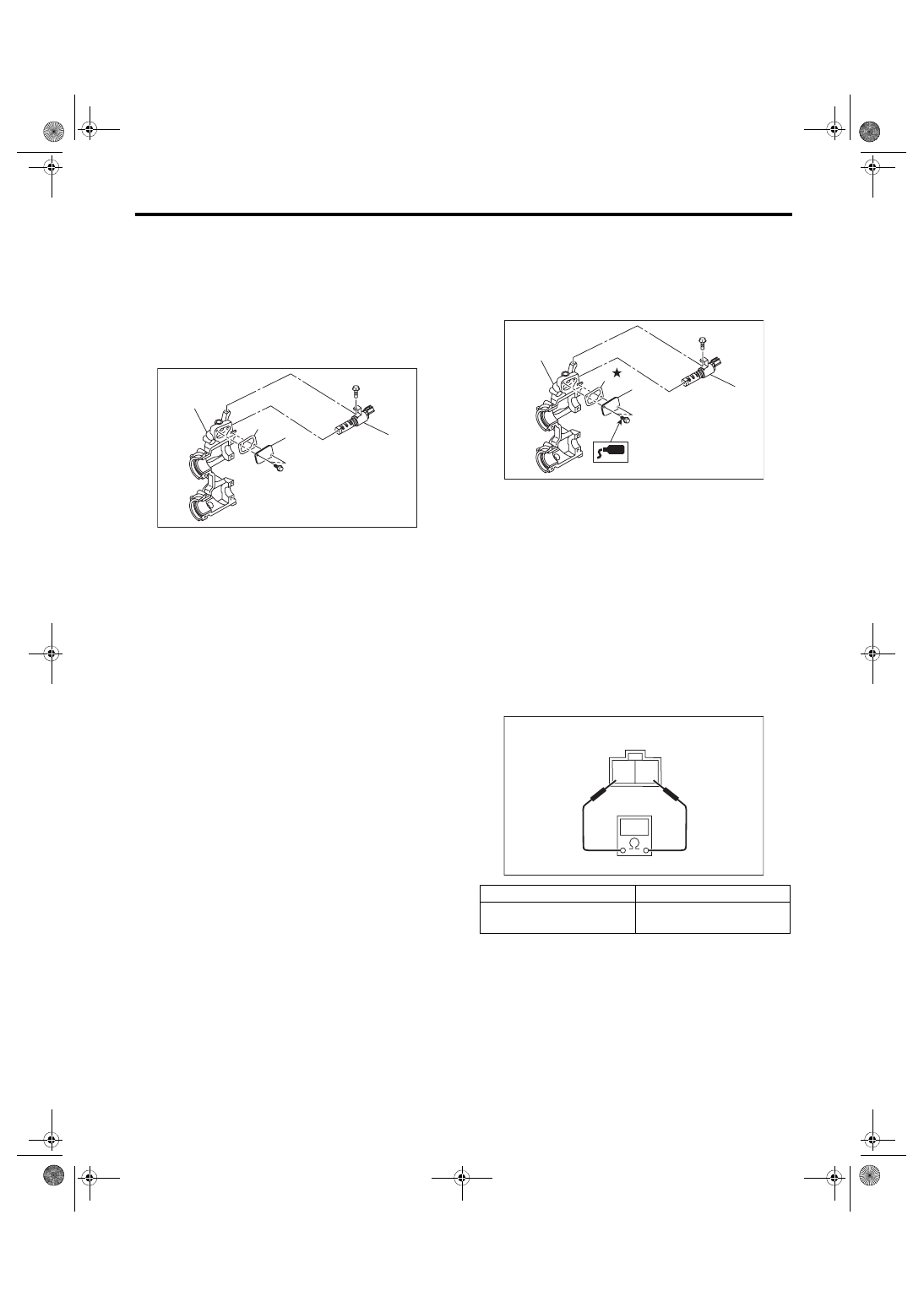
1) Remove the two mounting bolts securing oil re-
turn cover, and remove the oil return cover and
gasket.
2) Remove the bolt securing oil flow control sole-
noid valve, and remove the oil flow control solenoid
valve.
2. EXHAUST SIDE
The oil flow control solenoid valve on the exhaust
side cannot be disassembled.
D: ASSEMBLY
1. INTAKE SIDE
1) Install the oil flow control solenoid valve.
Tightening torque:
6.4 N·m (0.7 kgf-m, 4.7 ft-lb)
2) Apply liquid gasket to the two bolts securing oil
return cover.
Liquid gasket:
THREE BOND 1324 (Part No. 004403042)
3) Attach the oil return cover and gasket.
Tightening torque:
9 N·m (0.9 kgf-m, 6.6 ft-lb)
NOTE:
Use a new gasket.
2. EXHAUST SIDE
The oil flow control solenoid valve on the exhaust
side cannot be disassembled.
E: INSPECTION
1) Check that the oil flow control solenoid valve has
no deformation, cracks or other damages.
2) Measure the resistance between the oil flow
control solenoid valve terminals.
(A) Oil flow control solenoid valve
(B) Oil return cover
(C) Gasket
(D) Front camshaft cap
FU-05699
(A)
(D)
(C)
(B)
(A) Oil flow control solenoid valve
(B) Oil return cover
(C) Gasket
(D) Front camshaft cap
Terminal No.
Standard
1 and 2
7.4±0.5 Ω
(when 20°C (68°F))
FU-05700
(A)
(D)
(C)
(B)
2 1
EC-02428
Нет комментариевНе стесняйтесь поделиться с нами вашим ценным мнением.
Текст