Subaru Impreza 3 / Impreza WRX / Impreza WRX STI. Service manual — part 59
IN(STI)-18
Turbocharger
INTAKE (INDUCTION)
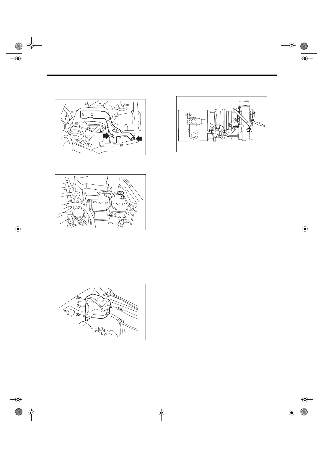
12) Install the intercooler stay.
Tightening torque:
16 N·m (1.6 kgf-m, 11.8 ft-lb)
13) Install the intercooler. <Ref. to IN(STI)-13, IN-
14) Connect the battery ground terminal.
15) Fill engine coolant. <Ref. to CO(STI)-13, FILL-
ING OF ENGINE COOLANT, REPLACEMENT,
C: INSPECTION
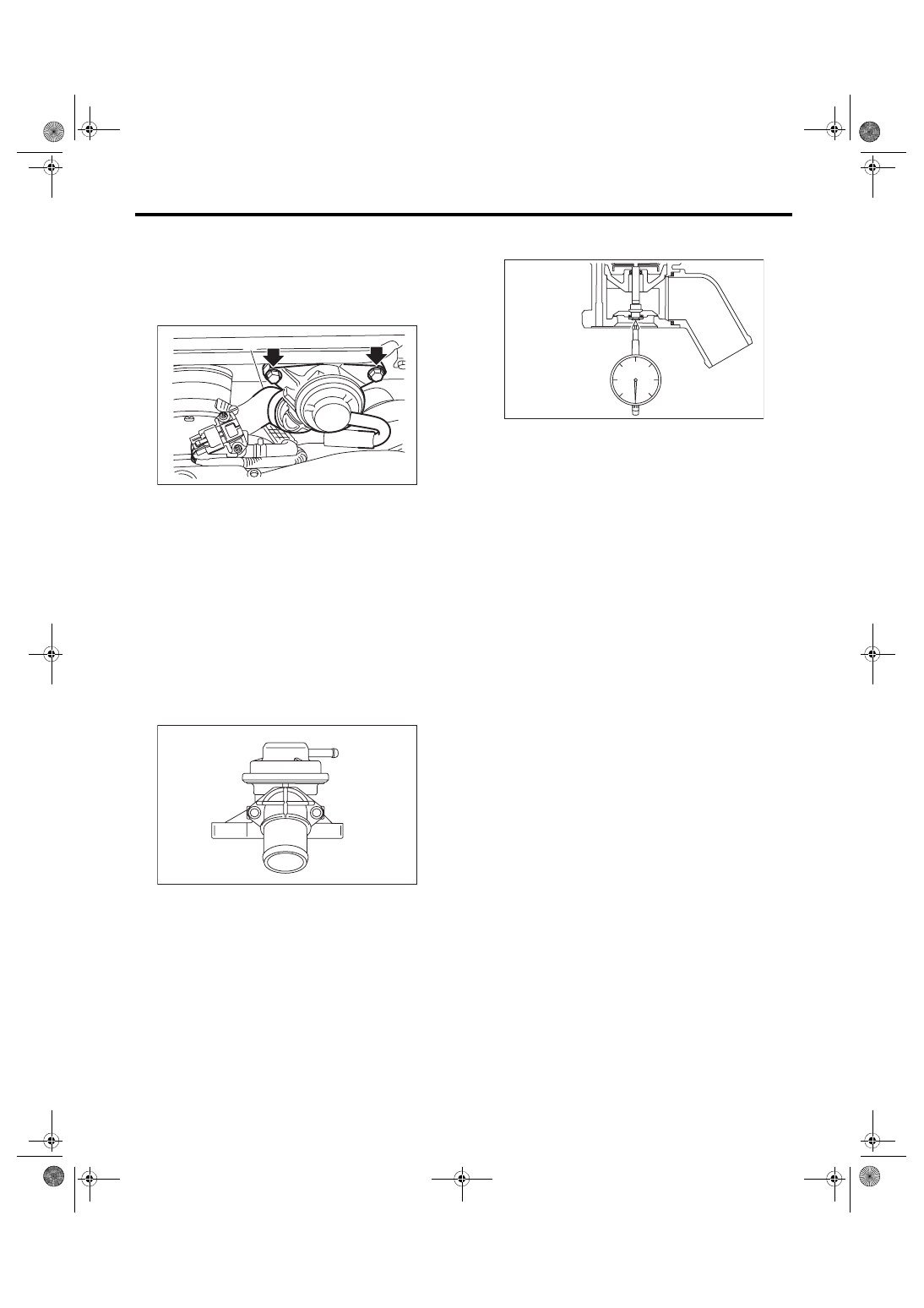
1. WASTE GATE ACTUATOR
1) Remove the intercooler. <Ref. to IN(STI)-12,
2) Remove the turbocharger upper cover.
3) Remove the boost hose (B) from the waste gate
actuator (A) of the turbocharger, and connect the
Mighty Vac to the waste gate actuator (A).
4) Pressurize slowly with the Mighty Vac, and mea-
sure the pressure when the control rod stroke (D)
becomes 2 mm (0.08 in). If it is not within the stan-
dard, replace the turbocharger assembly.
CAUTION:
Do not pressurize over 89.9 kPa (0.92 kgf/cm
2
,
13.0 psi) to prevent damaging the waste gate
actuator.
Operating pressure (control rod stroke 2 mm
(0.08 in)):
Standard
74.7 — 80.8 kPa
(0.76 — 0.82 kgf/cm
2
, 10.8 — 11.7 psi)
5) After inspection, install the related parts in the
reverse order of removal.
Tightening torque:
7.5 N·m (0.8 kgf-m, 5.5 ft-lb)
2. OTHER INSPECTIONS
1) Check that the turbocharger, turbocharger stay
and pipe have no deformation, cracks or other
damages.
2) Check that the hose and intake duct have no
cracks, damage or loose part.
3) Check that there are no oil leakage or water
leakage from the pipe attachment section.
EX-00007
IN-00203
EX-02662
(A) Waste gate actuator
(B) Boost hose
(C) Control rod
(D) Control rod stroke
(C)
(B)
(A)
IN-02942
(D)
IN(STI)-19
Air By-pass Valve
INTAKE (INDUCTION)
8. Air By-pass Valve
A: REMOVAL
Remove the air by-pass valve from the intercooler,
and then disconnect air by-pass hose (A) and vac-
uum hose (B) from the air by-pass valve.
B: INSTALLATION
Install in the reverse order of removal.
NOTE:
Use a new gasket.
Tightening torque:
16 N·m (1.6 kgf-m, 11.8 ft-lb)
C: INSPECTION
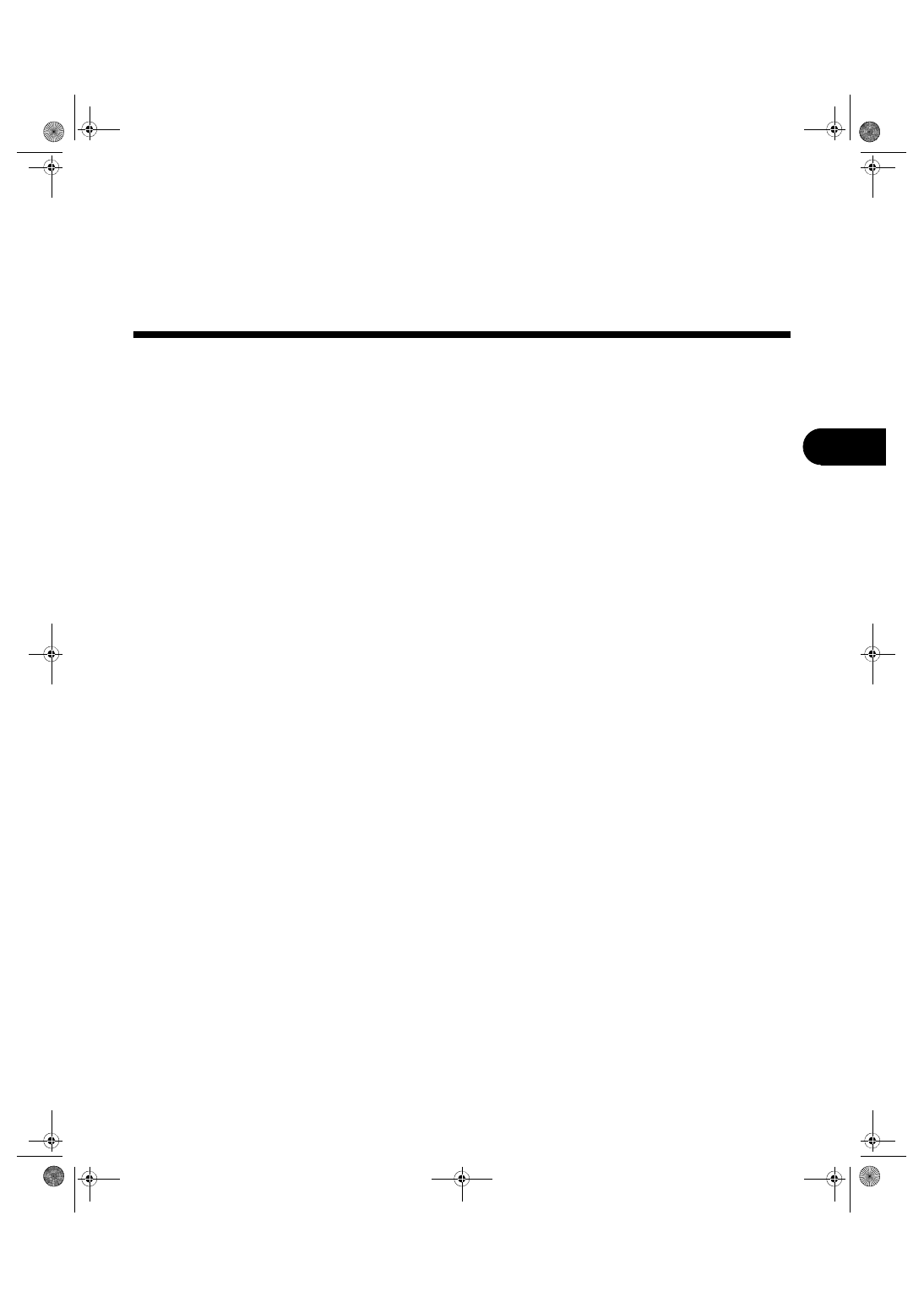
1. AIR BY-PASS VALVE
1) Check that the air by-pass valve has no defor-
mation, cracks or other damages.
2) Connect the Mighty Vac to the nipple (A) of the
air by-pass valve.
3) Using the Mighty Vac, generate the vacuum pres-
sure to –93.3 kPa (–0.95 kgf/cm
2
, –13.5 psi). Check
that the Mighty Vac gauge needle holds 10 seconds
without falling by –92.6 kPa (–0.94 kgf/cm
2
, –13.4
psi).
4) Set a dial gauge to the end of valve rod of the air
by-pass valve.
5) Slowly generate vacuum pressure with the
Mighty Vac and check the pressure when the nee-
dle of the dial gauge (valve stroke) becomes 0.5
mm (0.02 in). If it is not within the standard, replace
the air by-pass valve.
Opening pressure (valve stroke 0.5 mm (0.02
in)):
Standard
–62.7 — –70.7 kPa
(–0.64 — –0.72 kgf/cm
2
, –9.09 — –10.3 psi)
6) Increase vacuum pressure more than 5) and
check the pressure when the needle of the dial
gauge (valve stroke) becomes 7.5 mm (0.3 in). If it
is not within the standard, replace the air by-pass
valve.
Full open pressure (valve stroke 7.5 mm (0.3
in)):
Standard
–102.7 — –117.3 kPa
(–1.05 — –1.20 kgf/cm
2
, –14.9 — –17.0 psi)
2. OTHER INSPECTIONS
Check that the vacuum hose and air by-pass pipe
have no cracks, damage or loose part.
IN-03501
(B)
(A)
IN-02606
(A)
IN-02607
IN(STI)-20
Resonator Chamber
INTAKE (INDUCTION)
9. Resonator Chamber
A: REMOVAL
The resonator chamber and air cleaner case are in-
tegrated into one unit; therefore, refer to “Air Clean-
er Case” for removal procedure. <Ref. to IN(STI)-8,
B: INSTALLATION
The resonator chamber and air cleaner case are in-
tegrated into one unit; therefore, refer to “Air Clean-
er Case” for installation procedure. <Ref. to
IN(STI)-8, INSTALLATION, Air Cleaner Case.>
C: INSPECTION
Check that the resonator chamber has no deforma-
tion, cracks or other damages.
MECHANICAL
ME(STI)
Page
General Description . . . . . . . . . . . . . . . . . . . . ...2
Compression . . . . . . . . . . . . . . . . . . . . . . . 20
Idle Speed . . . . . . . . . . . . . . . . . . . . . . . . 21
Ignition Timing . . . . . . . . . . . . . . . . . . . . . . ..22
Intake Manifold Vacuum . . . . . . . . . . . . . . . . . . ...23
Engine Oil Pressure . . . . . . . . . . . . . . . . . . . . .24
Fuel Pressure . . . . . . . . . . . . . . . . . . . . . . ...25
Valve Clearance . . . . . . . . . . . . . . . . . . . . . ...26
Engine Assembly . . . . . . . . . . . . . . . . . . . . . .30
Engine Mounting . . . . . . . . . . . . . . . . . . . . . ..38
Preparation for Overhaul . . . . . . . . . . . . . . . . . . ..39
V-belt . . . . . . . . . . . . . . . . . . . . . . . . . . 40
Crank Pulley . . . . . . . . . . . . . . . . . . . . . . . .47
Timing Belt Cover . . . . . . . . . . . . . . . . . . . . . .49
Timing Belt . . . . . . . . . . . . . . . . . . . . . . . ...50
Cam Sprocket . . . . . . . . . . . . . . . . . . . . . . ..59
Crank Sprocket . . . . . . . . . . . . . . . . . . . . . . 60
Camshaft . . . . . . . . . . . . . . . . . . . . . . . . ..61
Cylinder Head . . . . . . . . . . . . . . . . . . . . . . ..70
Cylinder Block . . . . . . . . . . . . . . . . . . . . . . ..80
Intake and Exhaust Valve . . . . . . . . . . . . . . . . . ..103
Piston . . . . . . . . . . . . . . . . . . . . . . . . . .104
Connecting Rod . . . . . . . . . . . . . . . . . . . . . .105
Crankshaft . . . . . . . . . . . . . . . . . . . . . . . ..106
Engine Trouble in General . . . . . . . . . . . . . . . . . .107
Engine Noise . . . . . . . . . . . . . . . . . . . . . . ..113
Нет комментариевНе стесняйтесь поделиться с нами вашим ценным мнением.
Текст