Subaru Impreza 3 / Impreza WRX / Impreza WRX STI. Service manual — part 58
IN(STI)-14
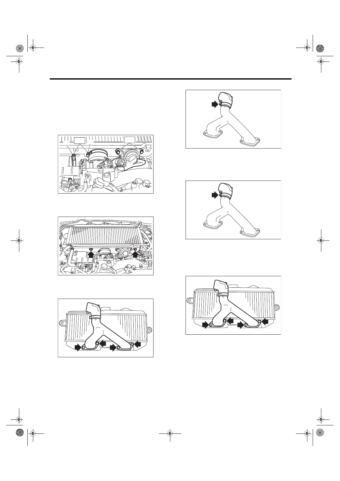
Intercooler
INTAKE (INDUCTION)
7) Install the bolts (C) which secures the air by-
pass valve to the intercooler, and install the air by-
pass valve.
NOTE:
Use a new gasket.
Tightening torque:
T1: 3 N·m (0.3 kgf-m, 2.2 ft-lb)
T2: 16 N·m (1.6 kgf-m, 11.8 ft-lb)
8) Install the PCV pipe to the intercooler.
Tightening torque:
5.5 N·m (0.6 kgf-m, 4.1 ft-lb)
C: DISASSEMBLY
1) Remove the intercooler duct from the intercool-
er.
2) Remove the intake duct from intercooler duct.
D: ASSEMBLY
1) Install the intake duct to the intercooler duct.
Tightening torque:
3 N·m (0.3 kgf-m, 2.2 ft-lb)
2) Install the intercooler duct to the intercooler.
NOTE:
Use a new gasket.
Tightening torque:
16 N·m (1.6 kgf-m, 11.8 ft-lb)
E: INSPECTION
1) Check that the intercooler and intercooler duct
have no deformation, cracks or other damages.
2) Check that the hose and intake duct have no
cracks, damage or loose part.
IN-03502
(A)
(B)
(C)
T1
T2
IN-03078
IN-03496
IN-02350
IN-02350
IN-03496
IN(STI)-15
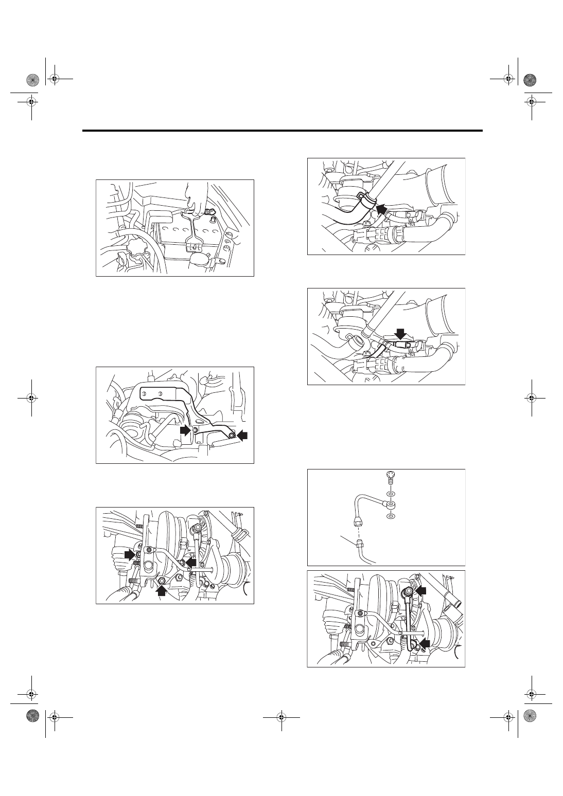
Turbocharger
INTAKE (INDUCTION)
7. Turbocharger
A: REMOVAL
1) Disconnect the ground cable from battery.
2) Lift up the vehicle.
3) Drain approximately 3.0 L (3.2 US qt, 2.6 Imp qt)
of coolant. <Ref. to CO(STI)-13, DRAINING OF
ENGINE COOLANT, REPLACEMENT, Engine
4) Lower the vehicle.
5) Remove the intercooler. <Ref. to IN(STI)-12,
6) Remove the intercooler stay.
7) Remove the center exhaust pipe. <Ref. to
EX(STI)-8, REMOVAL, Center Exhaust Pipe.>
8) Lower the vehicle.
9) Remove the joint pipe from the turbocharger.
10) Disconnect the engine coolant hose from the
upper side of the water pipe.
11) Disconnect the air control hose (A), and loosen
the clamp holding the intake duct to the turbocharg-
er.
12) Remove the oil inlet pipe from the turbocharg-
er.
CAUTION:
In order to prevent damaging the oil pipe on the
cylinder head side, fix the section (a) shown in
the figure when loosing the oil inlet pipe flare
nut, and avoid the part from rotating together
while loosening the nut.
IN-00203
EX-00007
IN-02390
IN-02594
IN-02930
(A)
(a)
IN-02955
IN-02633
IN(STI)-16
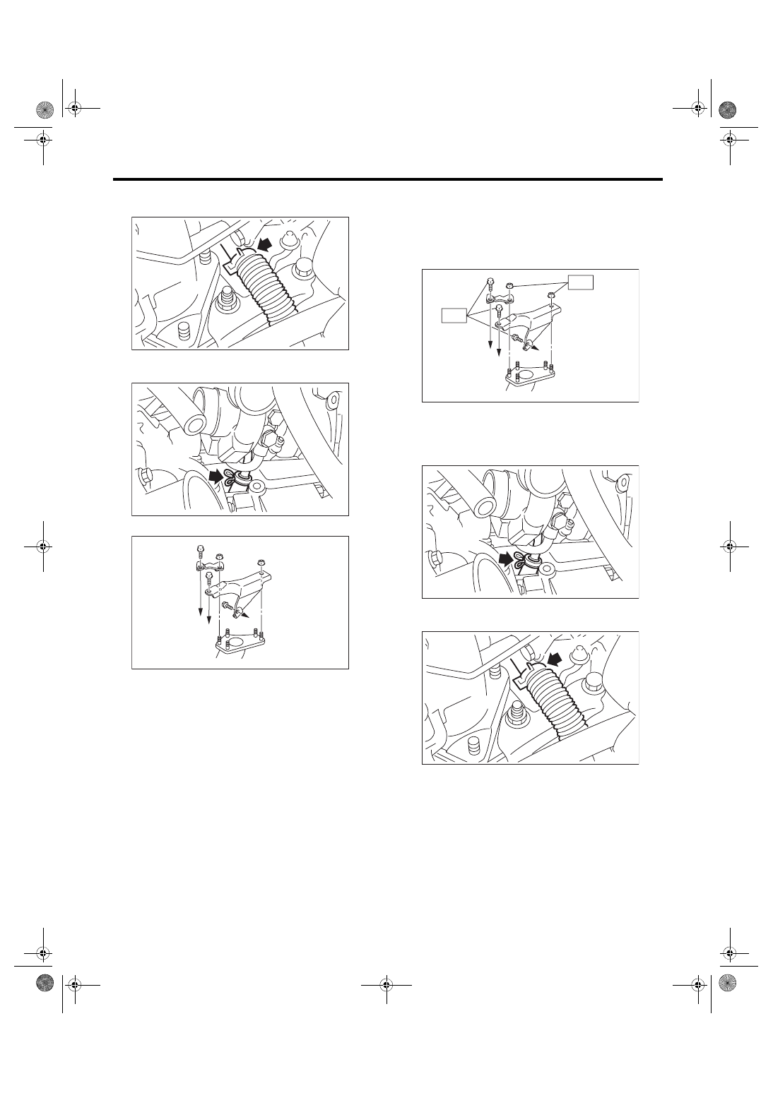
Turbocharger
INTAKE (INDUCTION)
13) Disconnect the engine coolant hose from the
lower side of the water pipe.
14) Disconnect the oil outlet hose from the oil outlet
pipe, and remove the turbocharger.
15) Remove the turbocharger stay.
B: INSTALLATION
1) Install the turbocharger stay.
Tightening torque:
T1: 33 N·m (3.4 kgf-m, 24.3 ft-lb)
T2: 42.5 N·m (4.3 kgf-m, 31.3 ft-lb)
2) Connect the oil outlet hose to the oil outlet pipe.
3) Connect the engine coolant hose to the lower
side of the water pipe.
(A) To cylinder head RH
(B) To cylinder block RH
IN-02931
IN-02310
IN-02859
(A)
(A)
(B)
(A) To cylinder head RH
(B) To cylinder block RH
T1
IN-02860
(A)
(A)
(B)
T2
IN-02310
IN-02931
IN(STI)-17
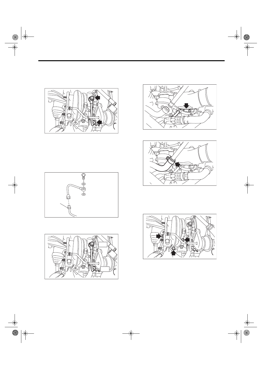
Turbocharger
INTAKE (INDUCTION)
4) Temporarily tighten the union bolts and flare
nuts which secure the oil inlet pipe to the turbo-
charger.
NOTE:
Use a new gasket.
5) Tighten the union bolts and flare nuts which se-
cure the oil inlet pipe to the turbocharger.
CAUTION:
In order to prevent damaging the oil pipe on the
cylinder head side, fix the section (a) shown in
the figure when tightening the oil inlet pipe flare
nut, and avoid the part from rotating together
while tightening the nut.
Tightening torque:
T1: 16 N·m (1.6 kgf-m, 11.8 ft-lb)
T2: 20 N·m (2.0 kgf-m, 14.8 ft-lb)
6) Connect the air control hose (A), and install the
intake duct to the turbocharger.
Tightening torque:
3 N·m (0.3 kgf-m, 2.2 ft-lb)
7) Connect the engine coolant hoses to the upper
side of the water pipe.
8) Install the joint pipe to turbocharger.
NOTE:
Use a new gasket.
Tightening torque:
42.5 N·m (4.3 kgf-m, 31.3 ft-lb)
9) Lift up the vehicle.
10) Install the center exhaust pipe. <Ref. to
EX(STI)-9, INSTALLATION, Center Exhaust
11) Lower the vehicle.
IN-02633
(a)
IN-02955
IN-02613
T1
T2
IN-02930
(A)
IN-02594
IN-02390
Нет комментариевНе стесняйтесь поделиться с нами вашим ценным мнением.
Текст