Subaru Impreza 3 / Impreza WRX / Impreza WRX STI. Service manual — part 500
DI-45
Rear Differential (T-type)
DIFFERENTIALS
12) When the bearing preload is out of the speci-
fied range, select the preload adjusting washer and
spacer from the following table in order to make it
within the specified range.
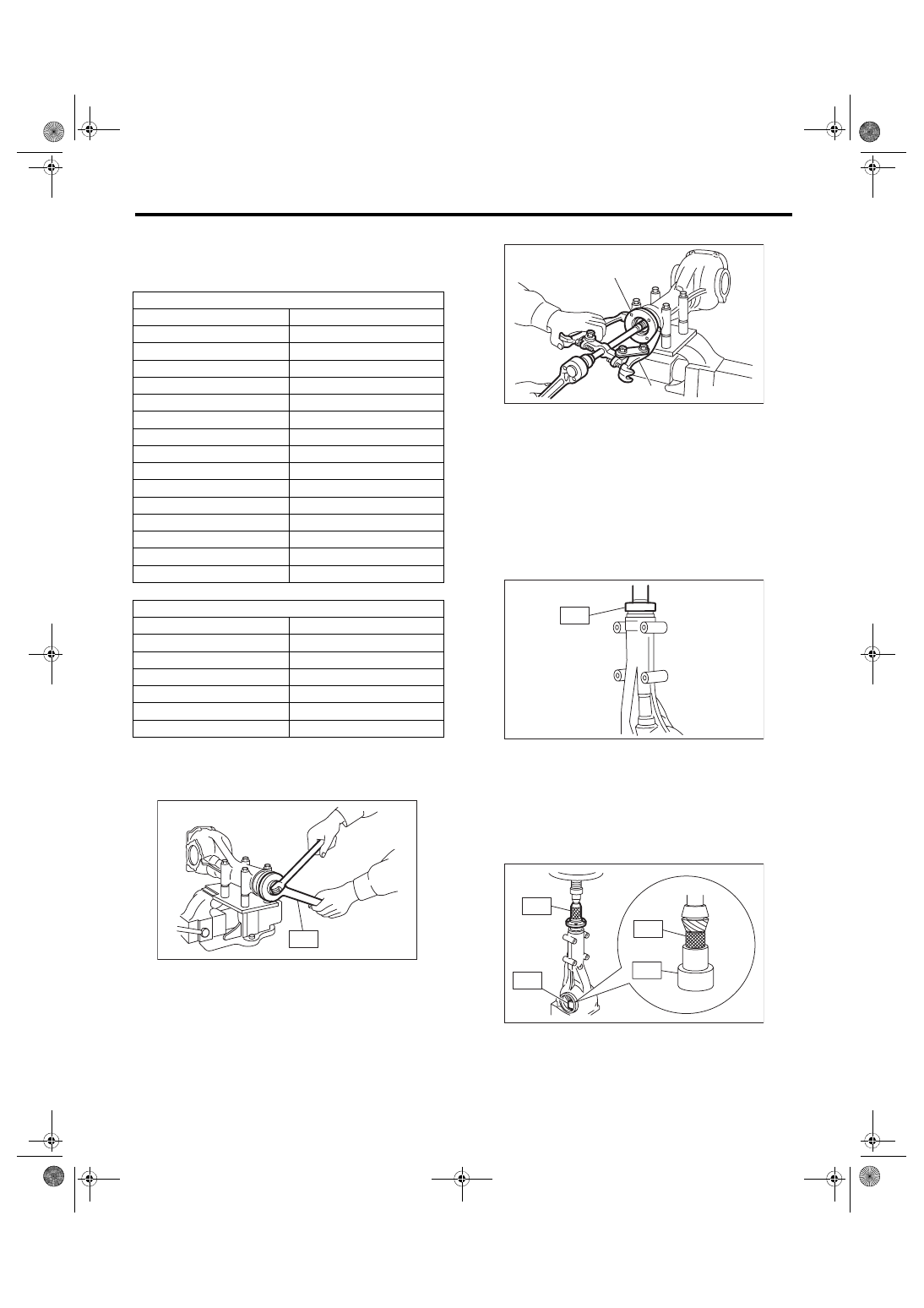
13) Remove the self-locking nut while securing the
companion flange with ST.
ST 18633AA000 WRENCH COMPL
14) Extract the companion flange with a puller.
15) Using the ST, install the oil seal.
NOTE:
• Use a new oil seal.
• Press-fit until the oil seal end comes 1 mm (0.04
in) inward from end of carrier.
• Apply differential gear oil to the oil seal lips.
ST 498447120
INSTALLER
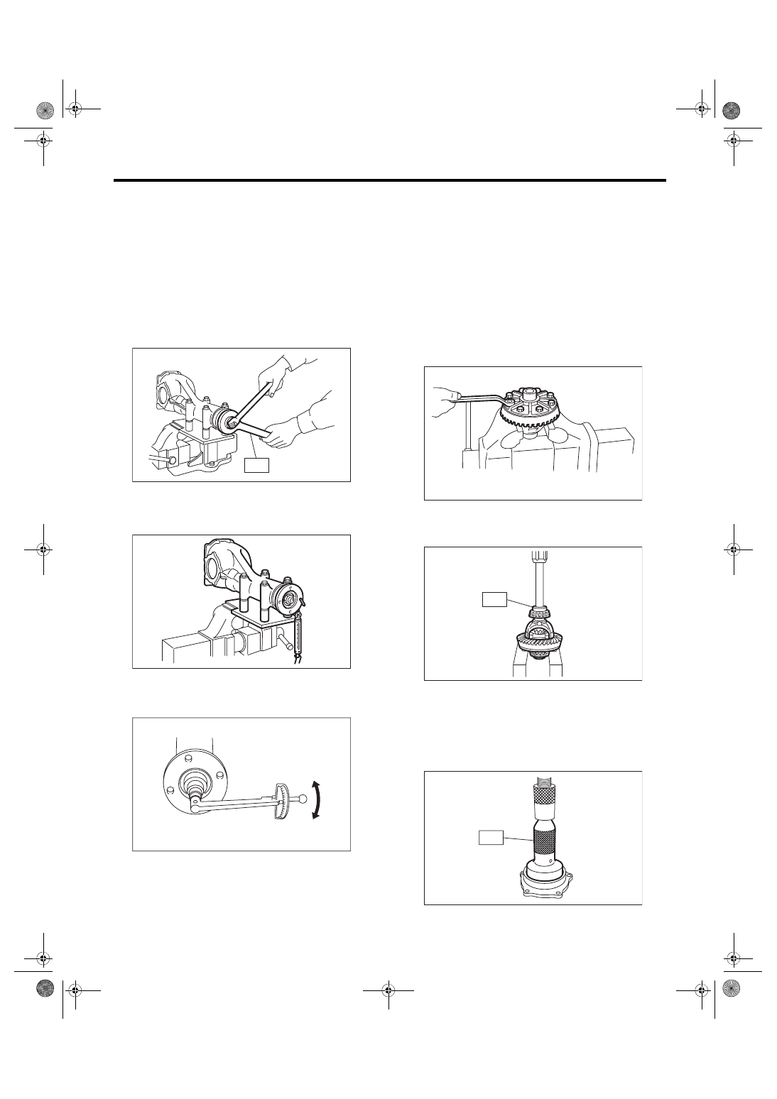
16) Press-fit the companion flange with ST1, ST2,
and ST3.
ST1 899874100
INSTALLER
ST2 399780104
WEIGHT
ST3 498937110
HOLDER DRIVE PINION
NOTE:
Be careful not to damage the bearing.
Preload adjusting washer
Part No.
Thickness mm (in)
383705200
2.59 (0.1020)
383715200
2.57 (0.1012)
383725200
2.55 (0.1004)
383735200
2.53 (0.0996)
383745200
2.51 (0.0988)
383755200
2.49 (0.0980)
383765200
2.47 (0.0972)
383775200
2.45 (0.0965)
383785200
2.43 (0.0957)
383795200
2.41 (0.0949)
383805200
2.39 (0.0941)
383815200
2.37 (0.0933)
383825200
2.35 (0.0925)
383835200
2.33 (0.0917)
383845200
2.31 (0.0909)
Preload adjusting spacer
Part No.
Length mm (in)
31454AA130
52.2 (2.055)
31454AA140
52.4 (2.063)
31454AA150
52.6 (2.071)
31454AA160
52.8 (2.079)
31454AA170
53.0 (2.087)
31454AA180
53.2 (2.094)
DI-00091
ST
(A) Companion flange
(B) Puller
DI-00142
(B)
(A)
DI-00089
ST
ST3
ST1
ST2
ST2
DI-00323
DI-46
Rear Differential (T-type)
DIFFERENTIALS
17) Apply seal material on the drive pinion shaft
thread and new self-locking nut seat.
Seal material:
THREE BOND 1324 (Part No. 004403042) or
equivalent
18) Attach the new self-locking nut and use the ST
to fix the companion flange in place, then tighten
the self-locking nut.
Tightening torque:
181.5 N·m (18.5 kgf-m, 133.9 ft-lb)
ST 18633AA000 WRENCH COMPL
19) Check the initial torque or initial load.
Initial load:
24.1 — 38.6 N (2.5 — 3.9 kgf, 5.4 — 8.7 lbf)
Initial torque:
0.98 — 1.57 N·m (0.10 — 0.16 kgf-m, 0.72 —
1.16 ft-lb)
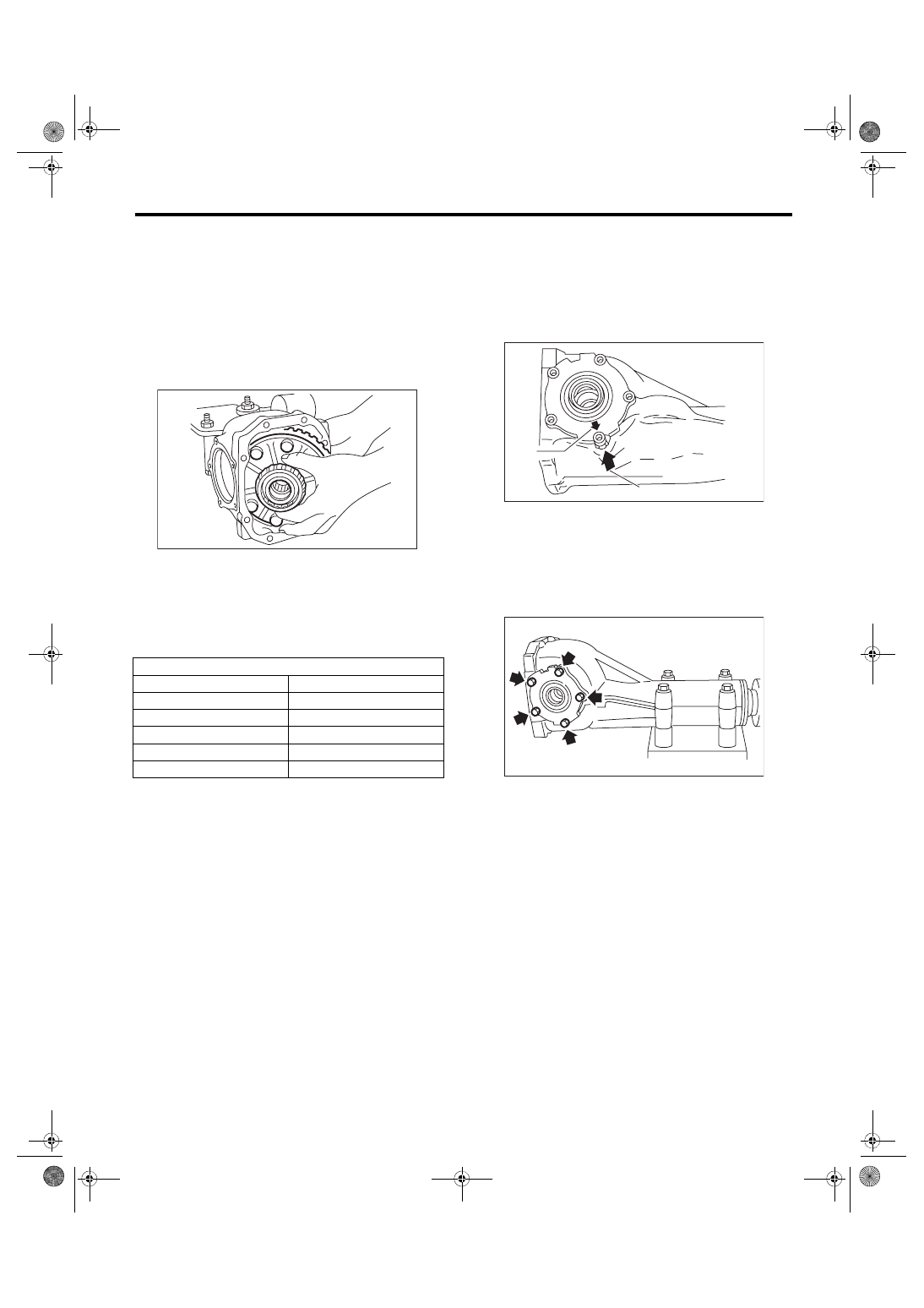
20) Install the driven gear to the differential case.
NOTE:
• Before installing bolts, apply seal material to bolt
threads.
Seal material:
THREE BOND 1324 (Part No. 004403042) or
equivalent
• Make sure there is no clearance between the dif-
ferential case and driven gear.
• Tighten opposing bolts in order.
Tightening torque:
103 N·m (10.5 kgf-m, 76.0 ft-lb)
21) Using the ST, press-fit the side bearing to the
differential case.
ST 398487700
DRIFT
22) Using the ST, press-fit the side bearing outer
race to the side retainer.
CAUTION:
Make sure that the bearing outer races and
cones are properly assembled.
ST 398417700
DRIFT
DI-00071
ST
DI-00715
DI-00481
DI-00068
DI-00095
ST
DI-00324
ST
DI-47
Rear Differential (T-type)
DIFFERENTIALS
23) Side retainer shim adjustment
(1) The hypoid driven gear backlash and side
bearing preload can be adjusted by the side re-
tainer shim thickness.
(2) Install the differential case assembly into dif-
ferential carrier in the reverse order of disas-
sembly.
NOTE:
Be careful not to hit the teeth of hypoid driven gear
against the differential carrier.
(3) Install the side retainer shim.
NOTE:
• Be careful not to mix up the side retainer shim
RH and LH.
• Replace broken or corroded side retainer shims
with a new part of the same thickness.
(4) During installation, align the arrow mark on
the differential carrier with the arrow mark on
the side retainer when installing the side retain-
er.
NOTE:
Be careful that side bearing outer race is not dam-
aged by the bearing roller.
(5) Tighten the side retainer bolts.
Tightening torque:
10.5 N·m (1.1 kgf-m, 7.7 ft-lb)
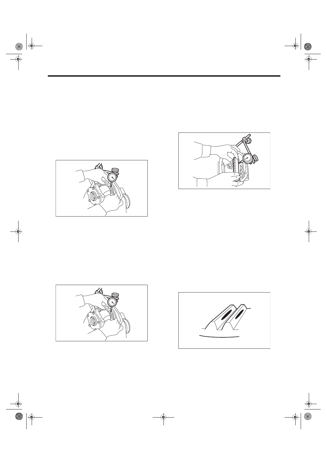
(6) Measure the hypoid driven gear to drive pin-
ion backlash. Set the magnet base on differen-
tial carrier. Align the contact point of dial gauge
with tooth face of hypoid driven gear, and move
hypoid driven gear while holding drive pinion
still. Read the value indicated on dial gauge. If
the backlash is outside the standard range, ad-
just the side retainer shim by the following
method.
Side retainer shim
Part No.
Thickness mm (in)
383475201
0.20 (0.0079)
383475202
0.25 (0.0098)
383475203
0.30 (0.0118)
383475204
0.40 (0.0157)
383475205
0.50 (0.0197)
DI-00065
(A) Arrow mark (on the side retainer)
(B) Arrow mark (on the differential carrier)
DI-00543
(B)
(A)
DI-00487
DI-48
Rear Differential (T-type)
DIFFERENTIALS
•
When backlash is less than 0.1 mm (0.004
in):
Reduce the thickness of shim on the back side
of the hypoid driven gear and increase the
thickness of shims on the teeth side of the hy-
poid driven gear.
•
When backlash exceeds 0.2 mm (0.008
in):
Increase the thickness of shim on the back side
of the hypoid driven gear and reduce the thick-
ness of shims on the teeth side of the hypoid
driven gear.
Backlash:
0.10 — 0.20 mm (0.004 — 0.008 in)
(7) Measure the total preload of the drive pin-
ion. If the total preload is not within specifica-
tion, adjust the thickness of side retainer shims,
increasing/reducing both shims by an even
amount on both sides.
Total preload:
26.5 — 53 N (2.7 — 5.4 kgf, 6.0 — 11.9 lbf)
24) Recheck the hypoid driven gear to drive pinion
backlash.
Backlash:
0.10 — 0.20 mm (0.004 — 0.008 in)
25) Check drive pinion and hypoid driven gears ro-
tate smoothly and make sure of the hypoid driven
gear runout on its back surface. If the runout on the
back side of the hypoid driven gear exceeds the
specification, check for any foreign material be-
tween the hypoid driven gear and differential case,
and for any deformation of the case or gear.
Hypoid driven gear back surface runout:
0.05 mm (0.002 in)
26) Checking and adjusting the tooth contact of hy-
poid driven gear
(1) Apply lead-free red dye evenly on the both
sides of three to four teeth of the hypoid driven
gear. Check the contact pattern after rotating
the hypoid driven gear several revolutions back
and forth until a definite contact pattern appears
on the hypoid driven gear.
(2) When the contact pattern is not correct, re-
adjust.
NOTE:
Be sure to wipe off the lead-free red dye completely
after the adjustment is completed.
• Correct tooth contact
Check item: Tooth contact pattern is slightly
shifted toward toe side under no-load rota-
tion. (When driving, it moves towards the
heel side.)
DI-00099
DI-00099
(A) Toe side
(B) Heel side
DI-00101
(A)
(B)
MT-01401
Нет комментариевНе стесняйтесь поделиться с нами вашим ценным мнением.
Текст