Subaru Impreza 3 / Impreza WRX / Impreza WRX STI. Service manual — part 304
EN(H4DOTC)(diag)-440
Diagnostic Procedure with Diagnostic Trouble Code (DTC)
ENGINE (DIAGNOSTICS)
Step
Check
Yes
No
1
CHECK CURRENT DATA.
1) Turn the ignition switch to ON.
2) Read the value of «Sec. Air Piping Pres-
sure» using Subaru Select Monitor.
NOTE:
Is the value of «Sec. Air Piping
Pressure» less than 53.3 kPa
(400 mmHg, 15.8 inHg)?
Even if DTC is
detected, the cir-
cuit has returned to
a normal condition
at this time. Repro-
duce the failure,
and then perform
the diagnosis
again.
NOTE:
In this case, tem-
porary poor con-
tact of connector,
temporary open or
short circuit of har-
ness may be the
cause.
2
CHECK POWER SUPPLY OF SECONDARY
AIR COMBINATION VALVE.
1) Turn the ignition switch to OFF.
2) Disconnect the connectors from secondary
air combination valve RH (models without SI-
DRIVE) or LH (models with SI-DRIVE).
3) Turn the ignition switch to ON.
4) Measure the voltage between the second-
ary air combination valve RH or LH connector
and chassis ground.
Connector & terminal
Models without SI-DRIVE
(E41) No. 1 (+) — Chassis ground (–):
Models with SI-DRIVE
(E40) No. 1 (+) — Chassis ground (–):
Is the voltage 4.5 V or more?
Repair the harness
and connector.
NOTE:
In this case, repair
the following item:
• Open circuit in
harness between
ECM
connector
and secondary air
combination valve
RH or LH connec-
tor
• Poor contact of
ECM connector
• Poor contact of
coupling connector
3
CHECK HARNESS BETWEEN ECM AND
SECONDARY AIR COMBINATION VALVE
CONNECTOR.
1) Turn the ignition switch to OFF.
2) Disconnect the connector from ECM.
3) Measure the resistance of harness between
ECM connector and secondary air combination
valve RH or LH connector.
Connector & terminal
Models without SI-DRIVE
(B137) No. 9 — (E41) No. 2:
Models with SI-DRIVE
(B137) No. 9 — (E40) No. 2:
Is the resistance less than 1 Ω? Go to step
Repair the harness
and connector.
NOTE:
In this case, repair
the following item:
• Open circuit in
harness between
ECM
connector
and secondary air
combination valve
RH or LH connec-
tor
• Poor contact of
coupling connector
4
CHECK HARNESS BETWEEN ECM AND
SECONDARY AIR COMBINATION VALVE
CONNECTOR.
Measure the resistance between ECM connec-
tor and chassis ground.
Connector & terminal
(B137) No. 9 — Chassis ground:
Is the resistance 1 MΩ or
more?
Repair the ground
short circuit in har-
ness between
ECM connector
and secondary air
combination valve
RH or LH connec-
tor.
EN(H4DOTC)(diag)-441
Diagnostic Procedure with Diagnostic Trouble Code (DTC)
ENGINE (DIAGNOSTICS)
5
CHECK FOR POOR CONTACT.
Check for poor contact of the ECM and second-
ary air combination valve RH or LH connector.
Is there poor contact of ECM or
secondary air combination
valve RH or LH connector?
Repair the poor
contact of the ECM
or secondary air
combination valve
RH or LH connec-
tor.
Step
Check
Yes
No
EN(H4DOTC)(diag)-442
Diagnostic Procedure with Diagnostic Trouble Code (DTC)
ENGINE (DIAGNOSTICS)
FJ: DTC P2433 SECONDARY AIR INJECTION SYSTEM AIR FLOW /PRESSURE
SENSOR CIRCUIT HIGH
DTC DETECTING CONDITION:
• Immediately at fault recognition
• GENERAL DESCRIPTION <Ref. to GD(H4DOTC)-286, DTC P2433 SECONDARY AIR INJECTION SYS-
TEM AIR FLOW /PRESSURE SENSOR CIRCUIT HIGH, Diagnostic Trouble Code (DTC) Detecting Crite-
ria.>
CAUTION:
After servicing or replacing faulty parts, perform Clear Memory Mode <Ref. to EN(H4DOTC)(diag)-63,
OPERATION, Clear Memory Mode.>, and Inspection Mode <Ref. to EN(H4DOTC)(diag)-49, PROCE-
EN(H4DOTC)(diag)-443
Diagnostic Procedure with Diagnostic Trouble Code (DTC)
ENGINE (DIAGNOSTICS)
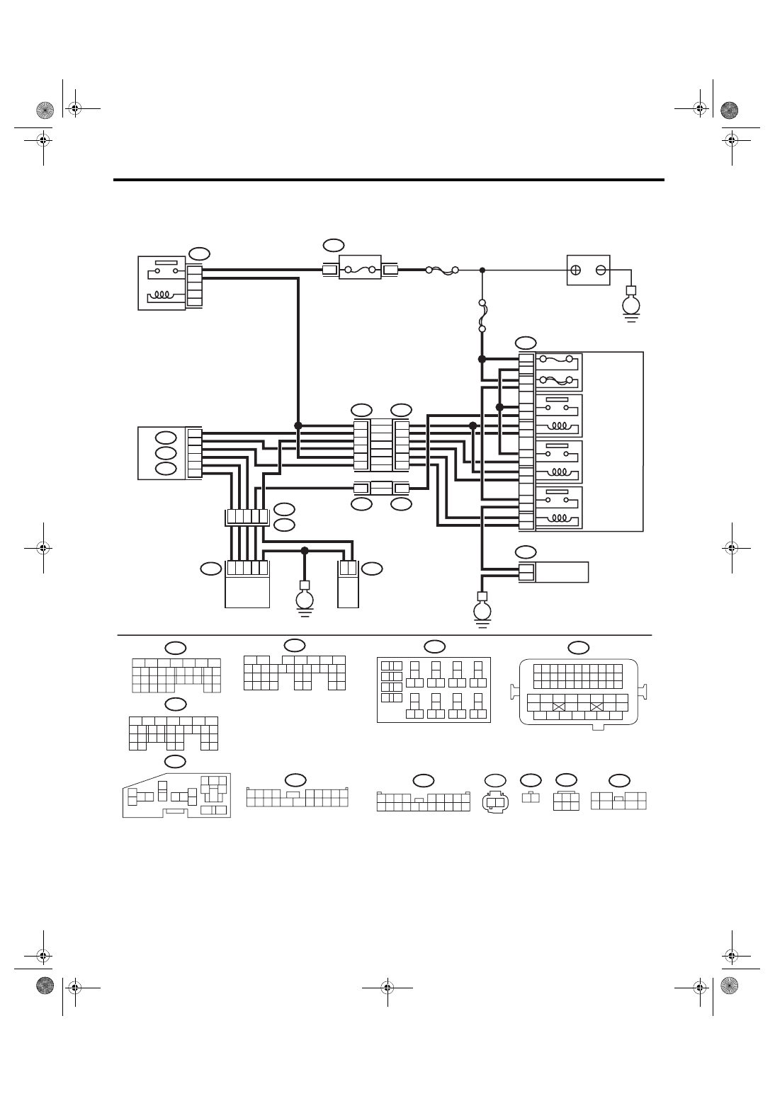
WIRING DIAGRAM:
• Models without SI-DRIVE <Ref. to WI-32, WITHOUT SI-DRIVE, WIRING DIAGRAM, Engine Electrical
EN-08734
F9
13
12
11
14
1
2
2
1
3
4
16
15
5
6
B143
F37
B144
B21
E2
E41
E40
B134
A:
A:
B135
B:
B135
B:
B137
D:
F37
F11
B144
F9
B143
F37
E41
10A
60A
9
10
8
7
11
5
20
8
B8
B20
B27
A19
D9
A29
6
1
2
8
47
3
2
1
6
4
1
2
9
2
16
18
14
12
10
4
14
4
E40
B134
46
B220
24
23
22
21
B137
D:
31
30
29
28
27
21
20
19
18
17
16
26
25
24
15
14
13
12
11
23
22
10
3
4
9
1
2
8
7
6
5
1 2
F11
29
4
3
1
2
7
6
5
10 11 12 13 14 15
25
24
16
30
9
8
17 18 19
20
28
21 22 23
32
31
26 27
33
34 35
B220
18
19
6
7
4
3
5
2
1
12
11
10
9
8
40
36 39
38
37
34
33
35
32
28 31
30
29
23
22
21
20
26
25
24
27
17
16
15
14
13
4
3
B220
15A
16
15
8
7
4
14
13
11
12
10
9
2
1
3
6
5
20
19
18
17
16
15
14
13
12
11
10
9
8
7
6
5
4
3
2
1
20
19
18
17
16
15
14
13
12
11
10
9
8
7
6
5
4
3
2
1
3
8
2
6
7
1
5
4
9
31
30
32
29
34
33
21
20
19
18
17
16
28
27
26
15
14
13
12
11
25
23
22
24
10
3
4
9
1
2
8
7
6
5
2
6
5
4
3
1
2
1
54
52 53
50 51
48 49
46 47
45
44
42 43
40 41
38 39
36 37
34 35
33
32
31
30
29
28
27
26
25
24
23
22
21
20
11
10
9
19
18
17
16
8
7
6
5
15
14
13
12
4
3
2
1
B21
E
E
E
ECM
SBF-7
FUSE
(RELAY BLOCK)
MAIN RELAY
SECONDARY
AIR COMBINATION
VALVE RELAY 2
MAIN SBF
SECONDARY
AIR PUMP
RELAY
SECONDARY
AIR COMBINATION
VALVE LH
SECONDARY
AIR COMBINATION
VALVE RH
(WITH BUILT-IN
PRESSURE SENSOR)
SECONDARY
AIR COMBINATION
VALVE RELAY 1
SECONDARY
AIR PUMP
MAIN FUSE BOX
(M/B)
RELAY HOLDER
BATTERY
Нет комментариевНе стесняйтесь поделиться с нами вашим ценным мнением.
Текст