Subaru Impreza 3 / Impreza WRX / Impreza WRX STI. Service manual — part 302
EN(H4DOTC)(diag)-432
Diagnostic Procedure with Diagnostic Trouble Code (DTC)
ENGINE (DIAGNOSTICS)
Step
Check
Yes
No
1
CHECK HARNESS BETWEEN ECM AND
LEAK CHECK VALVE ASSEMBLY CONNEC-
TOR.
1) Turn the ignition switch to ON.
2) Measure the voltage between ECM connec-
tor and chassis ground.
Connector & terminal
(B135) No. 4 (+) — Chassis ground (–):
Is the voltage 10 V or more?
2
CHECK FOR POOR CONTACT.
Check for poor contact of ECM connector.
Is there poor contact of ECM
connector?
Repair the poor
contact of ECM
connector.
Even if DTC is
detected, the cir-
cuit has returned to
a normal condition
at this time. Repro-
duce the failure,
and then perform
the diagnosis
again.
NOTE:
In this case, tem-
porary open or
short circuit of har-
ness or temporary
poor contact of
connector may be
the cause.
3
CHECK POWER SUPPLY TO LEAK CHECK
VALVE ASSEMBLY.
Measure the voltage between the leak check
valve assembly connector and engine ground.
Connector & terminal
(R400) No. 5 (+) — Engine ground (–):
Is the voltage 10 V or more?
Repair the power
supply circuit.
4
CHECK HARNESS BETWEEN ECM AND
LEAK CHECK VALVE ASSEMBLY CONNEC-
TOR.
1) Turn the ignition switch to OFF.
2) Disconnect the connector from ECM and
the leak check valve assembly.
3) Measure the resistance between leak check
valve assembly and chassis ground.
Connector & terminal
(R400) No. 1 — Chassis ground:
Is the resistance 1 MΩ or
more?
Repair the short
circuit to ground in
harness between
ECM connector
and leak check
valve assembly
connector.
5
CHECK HARNESS BETWEEN ECM AND
LEAK CHECK VALVE ASSEMBLY CONNEC-
TOR.
Measure the resistance of harness between
ECM connector and the leak check valve
assembly connector.
Connector & terminal
(B135) No. 4 — (R400) No. 1:
Is the resistance less than 1 Ω? Go to step
Repair the harness
and connector.
NOTE:
In this case, repair
the following item:
• Open circuit in
harness between
ECM
connector
and the leak check
valve
assembly
connector
• Poor contact of
coupling connector
EN(H4DOTC)(diag)-433
Diagnostic Procedure with Diagnostic Trouble Code (DTC)
ENGINE (DIAGNOSTICS)
6
CHECK LEAK CHECK VALVE ASSEMBLY.
Check the switching valve of the leak check
valve assembly. <Ref. to EC(STI)-20, CHECK
SWITCHING VALVE, INSPECTION, Leak
Check Valve Assembly.> <Ref. to EC(w/o STI)-
21, CHECK SWITCHING VALVE, INSPEC-
TION, Leak Check Valve Assembly.>
Is the switching valve of the
leak check valve assembly
OK?
Repair the poor
contact in the leak
check valve
assembly connec-
tor.
Step
Check
Yes
No
EN(H4DOTC)(diag)-434
Diagnostic Procedure with Diagnostic Trouble Code (DTC)
ENGINE (DIAGNOSTICS)
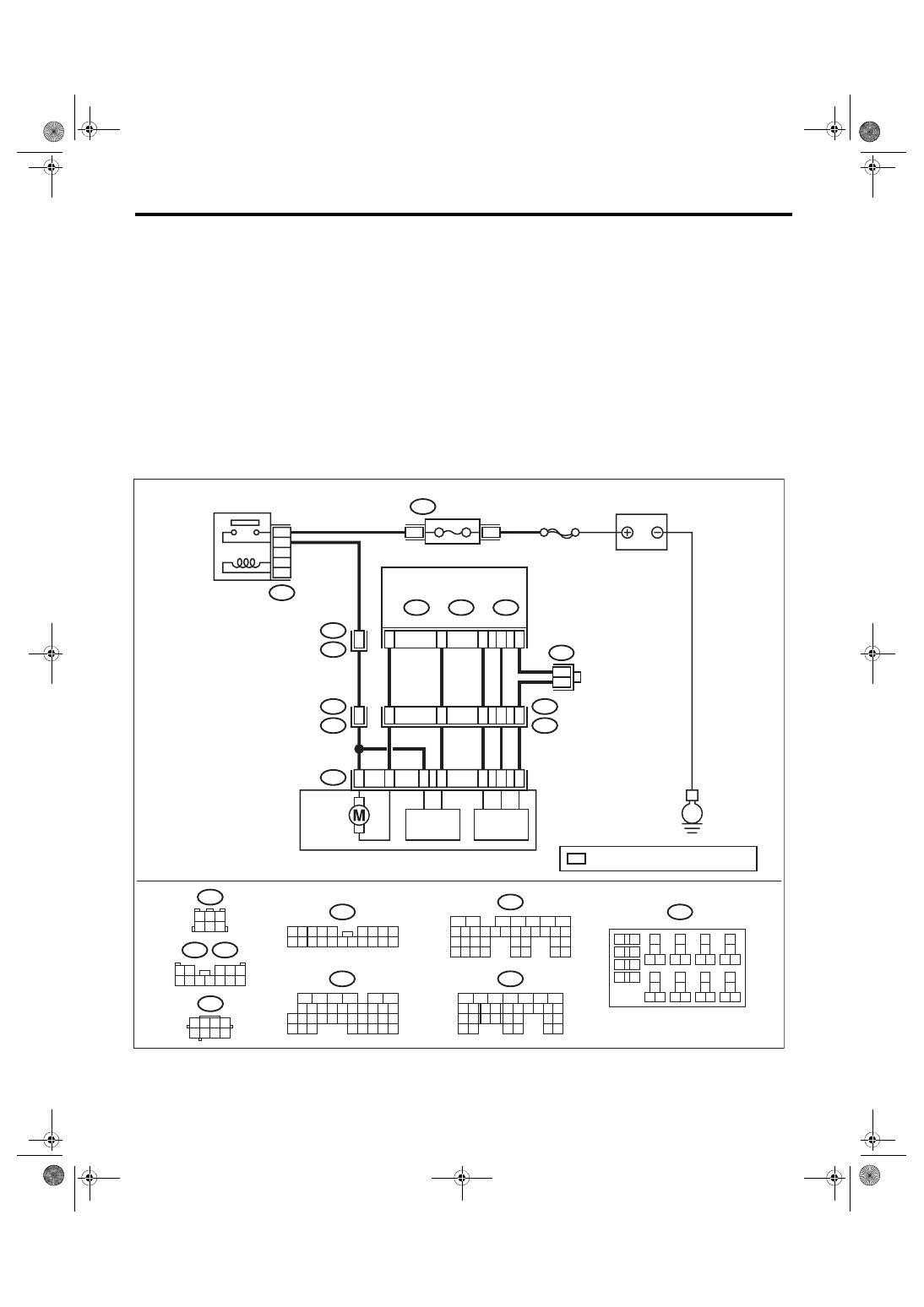
FG:DTC P2420 EVAPORATIVE EMISSION SYSTEM SWITCHING VALVE CON-
TROL CIRCUIT HIGH
DTC DETECTING CONDITION:
• Immediately at fault recognition
• GENERAL DESCRIPTION <Ref. to GD(H4DOTC)-282, DTC P2420 EVAPORATIVE EMISSION SYS-
TEM SWITCHING VALVE CONTROL CIRCUIT HIGH, Diagnostic Trouble Code (DTC) Detecting Criteria.>
CAUTION:
After servicing or replacing faulty parts, perform Clear Memory Mode <Ref. to EN(H4DOTC)(diag)-63,
OPERATION, Clear Memory Mode.>, and Inspection Mode <Ref. to EN(H4DOTC)(diag)-49, PROCE-
WIRING DIAGRAM:
• Engine electrical system, without SI-DRIVE <Ref. to WI-32, WITHOUT SI-DRIVE, WIRING DIAGRAM,
• Engine electrical system, with SI-DRIVE <Ref. to WI-48, WITH SI-DRIVE, WIRING DIAGRAM, Engine
ECM
B97
R1
10
B92
2 3 4 5
6 7 8 9
11 12 13 14
17 18 19 20
1
10
15 16
B97
R82
1 2
3 4 5
6 7 8 9 10 11 12
B220
B83
4
1 2 3
6
5
*
B83
*
*
D27
B22
C21
B30
B4
B135
B:
B136
C:
B137
D:
14
17
15
16
13
8
R81
R82
1
5
8
7
6
4
3
R400
5
6
7
8
2
1
9
4
3
10
24
22 23
25
11 12 13 14 15
26 27
28
16 17 18 19
20 21
29 30 31
32 33
34 35
B135
B:
5
6
7
8
2
1
9
4
3
10
22 23
11 12 13 14 15
24 25
26
16 17
18 19 20 21
27
28 29
30 31
B137
D:
16
10 11 12 13 14 15
25
24
30
9
8
7
17 18 19 20
28
21 22 23
29
32
31
1
2
3
4
5
6
27
26
33 34 35
B136
C:
1 2
4
5 6 7 8
3
R400
24
23
22
21
B220
13
14
15 16
17
27
24
25
26
20
21
22
23
29
30
31
28
32 35
33
34
37
38
39
36
40
8
9
10
11 12
1
2
5
3
4
7
6
19
18
B220
4
3
EN-09250
R5
B92
E
SBF-7
BATTERY
FUSE
(RELAY BLOCK)
MAIN RELAY
LEAK CHECK VALVE ASSY
VACUUM
PUMP
PRESSURE
SENSOR
SWITCHING
VALVE
: TERMINAL No. OPTIONAL ARRANGEMENT
EN(H4DOTC)(diag)-435
Diagnostic Procedure with Diagnostic Trouble Code (DTC)
ENGINE (DIAGNOSTICS)
Step
Check
Yes
No
1
CHECK HARNESS BETWEEN ECM AND
LEAK CHECK VALVE ASSEMBLY CONNEC-
TOR.
1) Turn the ignition switch to OFF.
2) Disconnect the connector from the leak
check valve assembly.
3) Turn the ignition switch to ON.
4) Measure the voltage between leak check
valve assembly and chassis ground.
Connector & terminal
(R400) No. 1 (+) — Chassis ground (–):
Is the voltage 10 V or more?
Repair the short
circuit to power in
harness between
ECM connector
and leak check
valve assembly
connector.
2
CHECK LEAK CHECK VALVE ASSEMBLY.
1) Turn the ignition switch to OFF.
2) Check the switching valve of the leak check
valve assembly. <Ref. to EC(STI)-20, CHECK
SWITCHING VALVE, INSPECTION, Leak
Check Valve Assembly.> <Ref. to EC(w/o STI)-
21, CHECK SWITCHING VALVE, INSPEC-
TION, Leak Check Valve Assembly.>
Is the switching valve of the
leak check valve assembly
OK?
Repair the poor
contact in the leak
check valve
assembly connec-
tor.
Нет комментариевНе стесняйтесь поделиться с нами вашим ценным мнением.
Текст