Subaru Impreza 3 / Impreza WRX / Impreza WRX STI. Service manual — part 388
CS-3
General Description
CONTROL SYSTEMS
B: COMPONENT
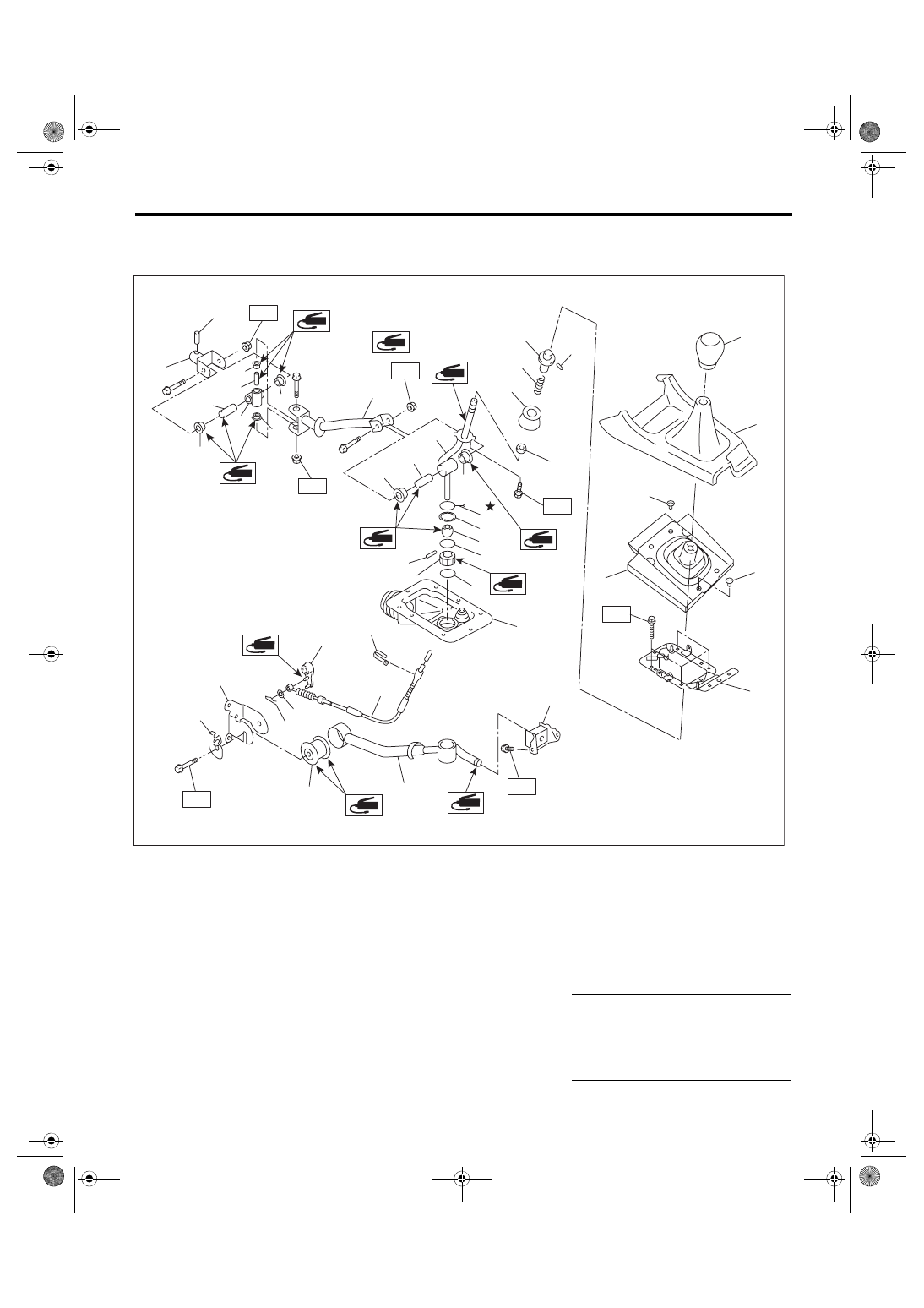
1. 6MT GEAR SHIFT LEVER
(1)
Gear shift knob
(15) Snap ring
(29) Snap pin
(2)
Console box front
(16) Bushing
(30) Bracket
(3)
Boot and insulator ASSY
(17) O-ring
(31) Cable plate
(4)
Clamp
(18) Spring pin
(32) Rod
(5)
Plate COMPL
(19) Bushing
(33) Spring pin
(6)
Slider
(20) O-ring
(34) Joint
(7)
Spring pin
(21) Boot
(35) Boss
(8)
Spring
(22) Cushion rubber
(9)
Holder
(23) Stay
Tightening torque: N·m (kgf-m, ft-lb)
(10) Seat cushion
(24) Bushing
T1: 1.3 (0.1, 1.0)
(11) Lever
(25) Reverse check cable
T2: 12 (1.2, 8.9)
(12) Bushing
(26) Band clip
T3: 18 (1.8, 13.3)
(13) Spacer
(27) Reverse check lever
T4: 32 (3.3, 23.6)
(14) Lock wire
(28) Washer
T3
T4
(5)
(4)
(6)
(3)
(2)
(1)
(23)
(24)
(25)
(19)
(20)
(21)
(22)
(18)
(17)
(16)
(13)
(15)
(14)
(12)
(11 )
(28)
(30)
(29)
(10)
(9)
(8)
(27)
(26)
(31)
(32)
CS-00925
(7)
(4)
(33)
(34)
(35)
(12)
(12)
(12)
(12)
(12)
(13)
(13)
T1
T2
T3
T2
T2
CS-4
General Description
CONTROL SYSTEMS
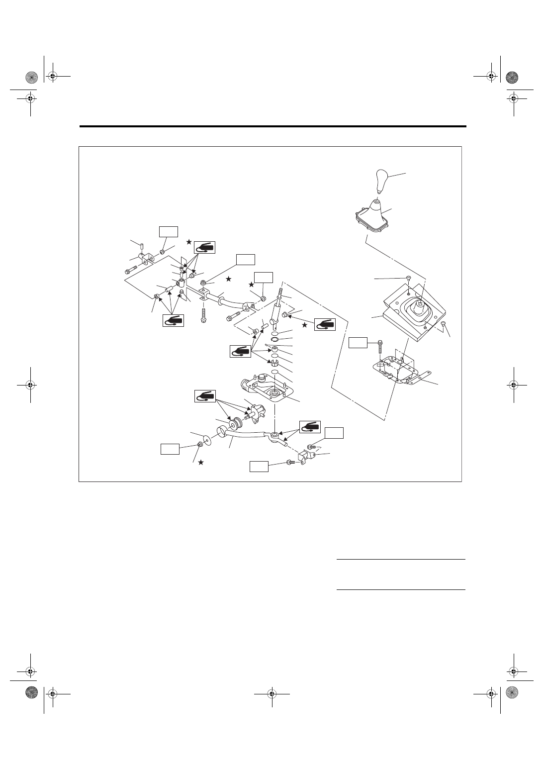
2. 5MT GEAR SHIFT LEVER
(1)
Gear shift knob
(11) O-ring
(21) Washer
(2)
Console boot
(12) Spring pin
(22) Stay
(3)
Clamp
(13) Bushing B
(23) Cushion rubber
(4)
Boot and insulator ASSY
(14) O-ring
(24) Boss
(5)
Plate COMPL
(15) Boot
(25) Bushing
(6)
Lever
(16) Spring pin
(26) Self-locking nut
(7)
Bushing
(17) Joint
(8)
Lock wire
(18) Rod
Tightening torque: N·m (kgf-m, ft-lb)
(9)
Snap ring
(19) Spacer
T1: 12 (1.2, 8.9)
(10) Bushing
(20) Bracket
T2: 18 (1.8, 13.3)
CS-01074
T2
T1
T2
T1
T2
(23)
(22)
(20)
(8)
(25)
(7)
(6)
(9)
(10)
(5)
(12)
(7)
(19)
(18)
(17)
(7)
(7)
(7)
(19)
(26)
(24)
(19)
(7)
(11)
(13)
(14)
(15)
(26)
(26)
(26)
(16)
(3)
(3)
(4)
(2)
(1)
(21)
T2
T1
CS-5
General Description
CONTROL SYSTEMS
C: CAUTION
• Wear appropriate work clothing, including a cap, protective goggles and protective shoes when performing
any work.
• Remove contamination including dirt and corrosion before removal, installation or disassembly.
• Keep the disassembled parts in order and protect them from dust and dirt.
• Before removal, installation or disassembly, be sure to clarify the failure. Avoid unnecessary removal, in-
stallation, disassembly and replacement.
• Use SUBARU genuine fluid, grease etc. or equivalent. Do not mix fluid, grease, etc. of different grades or
manufacturers.
• Be sure to tighten fasteners including bolts and nuts to the specified torque.
• Place shop jacks or rigid racks at the specified points.
• Apply grease onto sliding or revolving surfaces before installation.
• Before installing O-rings or snap rings, apply sufficient amount of fluid to avoid damage and deformation.
• Before securing a part in a vise, place cushioning material such as wood blocks, aluminum plate or cloth
between the part and the vise.
• Before disconnecting electrical connectors, be sure to disconnect the negative terminal from battery.
CS-6
MT Gear Shift Lever
CONTROL SYSTEMS
2. MT Gear Shift Lever
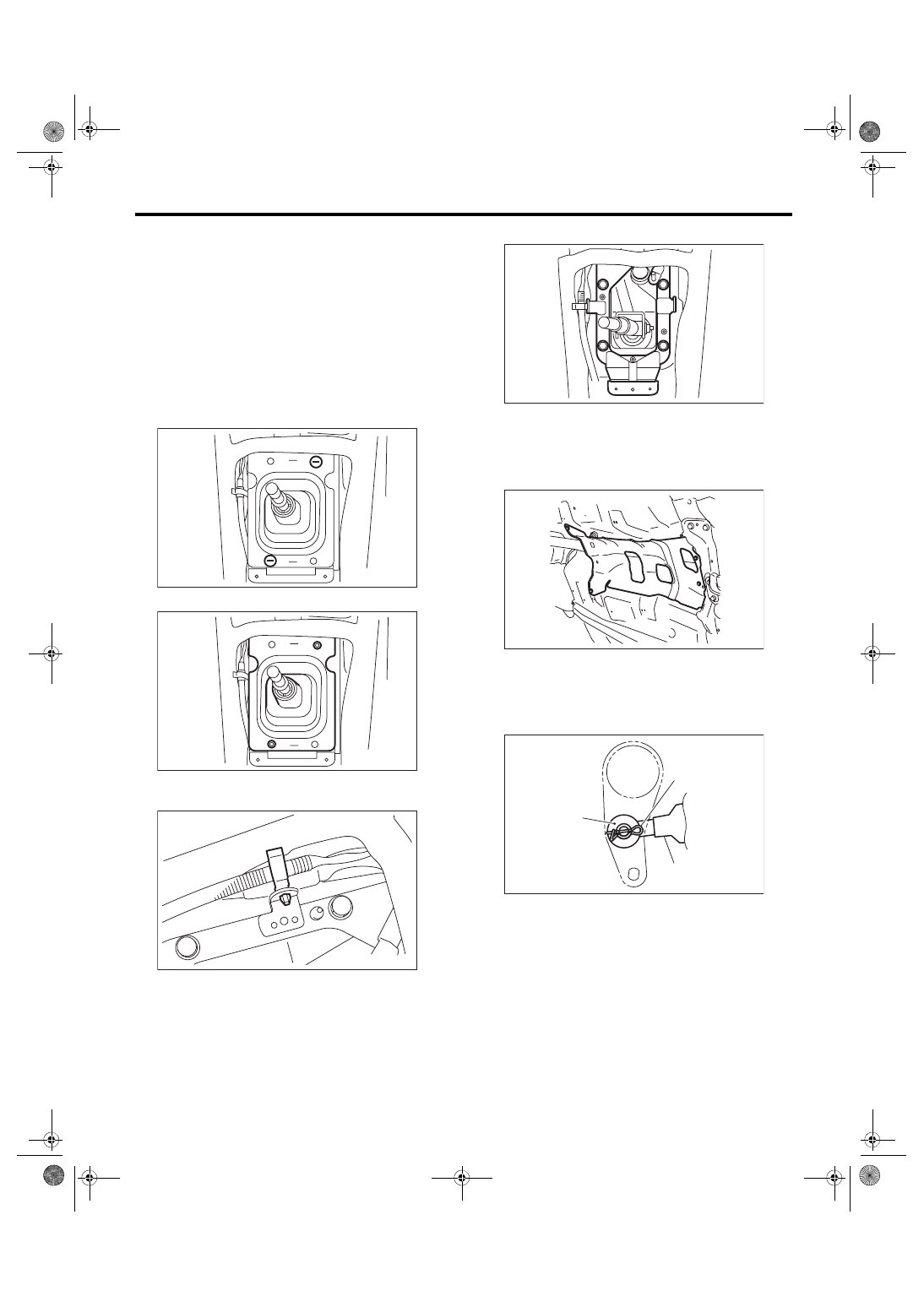
A: REMOVAL
1. STI MODEL
1) Disconnect the ground cable from battery.
2) Remove the gear shift knob.
3) Remove the console box. <Ref. to EI-51, RE-
4) Remove the console side cover and console
front panel. <Ref. to EI-52, CONSOLE FRONT
PANEL, REMOVAL, Center Console.>
5) Remove the clamp.
6) Remove the boot and insulator assembly.
7) Remove the harness clamp from the plate COM-
PL.
8) Remove the plate COMPL from the body.
9) Lift up the vehicle.
10) Remove the under cover.
11) Remove the center exhaust pipe. <Ref. to
EX(STI)-8, REMOVAL, Center Exhaust Pipe.>
12) Remove the heat shield cover.
13) Remove the crossmember. <Ref. to 6MT-29,
REMOVAL, Transmission Mounting System.>
14) Remove the snap pin and washer, and remove
the reverse check cable from the reverse check le-
ver.
CS-00926
CS-00927
CS-00581
(A) Snap pin
(B) Washer
(C) Reverse check cable
CS-00735
MT-01660
CS-00220
(B)
(A)
(C)
Нет комментариевНе стесняйтесь поделиться с нами вашим ценным мнением.
Текст