Subaru Impreza 3 / Impreza WRX / Impreza WRX STI. Service manual — part 760
CRUISE CONTROL SYSTEM
(DIAGNOSTICS)
CC(diag)
Page
Basic Diagnostic Procedure . . . . . . . . . . . . . . . . . ...2
General Description . . . . . . . . . . . . . . . . . . . . ...4
Electrical Component Location . . . . . . . . . . . . . . . . ..5
Engine Control Module (ECM) I/O Signal . . . . . . . . . . . . ..6
Subaru Select Monitor . . . . . . . . . . . . . . . . . . . . 7
Diagnostics with Phenomenon . . . . . . . . . . . . . . . . ...9
List of Cancel Code . . . . . . . . . . . . . . . . . . . . ..12
Diagnostic Procedure with Cancel Code . . . . . . . . . . . . ..14
CC(diag)-2
Basic Diagnostic Procedure
CRUISE CONTROL SYSTEM (DIAGNOSTICS)
1. Basic Diagnostic Procedure
A: PROCEDURE
Step
Check
Yes
No
1
CHECK MALFUNCTION INDICATOR LIGHT.
Make sure the malfunction indicator light illumi-
nates.
Does the malfunction indicator
light illuminate?
2
CHECK CRUISE INDICATOR LIGHT.
Make sure the cruise indicator light blinks.
Does the cruise indicator light
blink?
3
CHECK CRUISE CONTROL MAIN SWITCH
OPERATION.
Check cruise control main switch operation.
(Ensure the cruise indicator light illuminates.)
Is the cruise control main switch
turned on? (Does the cruise
indicator light illuminate?)
4
CHECK CRUISE CONTROL SET OPERA-
TION.
Check the cruise control setting operation.
Can the cruise control be set
while driving at 40 km/h (25
MPH) or more?
5
CHECK DTC.
Read all DTCs using the Subaru Select Monitor.
Is an engine or ABS/VDC
related DTC displayed?
6
CHECK FREEZE FRAME DATA.
Using the Subaru Select Monitor, check the
Freeze Frame Data or Information in Trouble
State.
Was the Freeze Frame Data or
Information in Trouble State
recorded?
Record the data.
Perform the diag-
nosis according to
the engine or ABS/
VDC related DTC.
Perform the diag-
nosis according to
the engine or ABS/
VDC related DTC.
7
CHECK CANCEL CODE.
Using the Subaru Select Monitor, read the can-
cel codes.
NOTE:
• Do not turn the ignition switch to OFF after the
cruise control is deactivated.
• Do not operate the cruise control command
switch after the cruise control is deactivated.
If the above is performed, the cancel code will
be cleared.
Is it possible to read the cancel
codes?
8
CHECK CRUISE SET INDICATOR LIGHT.
Make sure the cruise set indicator light illumi-
nates.
Does the cruise set indicator
light illuminate?
9
CHECK VEHICLE SPEED IS HELD WITHIN
SET SPEED.
Make sure the vehicle speed is held within set
speed.
Is the vehicle speed kept within
setting speed ±3 km/h (±2
MPH)? (Make sure that on a
level road.)
CC(diag)-3
Basic Diagnostic Procedure
CRUISE CONTROL SYSTEM (DIAGNOSTICS)
10
CHECK RESUME/ACCEL OPERATION.
Check the RESUME/ACCEL switch operation.
Does the vehicle speed
increase or return to set speed
after RESUME/ACCEL switch
has been pressed?
11
CHECK SET/COAST OPERATION.
Check the SET/COAST switch operation.
Does the vehicle speed
decrease after SET/COAST
switch has been pressed?
12
CANCEL OPERATION CHECK.
Check the CANCEL switch operation.
Is the cruise control released
after CANCEL switch has been
pressed?
13
CHECK CRUISE CONTROL RELEASE OP-
ERATION.
Check the cruise control release operation.
Is the cruise control released
after brake pedal has been
depressed?
14
CHECK CRUISE CONTROL RELEASE OP-
ERATION.
Check the cruise control release operation.
Is the cruise control released
after shifting to the neutral posi-
tion?
15
CHECK CRUISE CONTROL RELEASE OP-
ERATION.
Check the cruise control release operation.
Is the cruise control released
after depressing the clutch
pedal?
Finish the diagno-
sis.
Step
Check
Yes
No
CC(diag)-4
General Description
CRUISE CONTROL SYSTEM (DIAGNOSTICS)
2. General Description
A: CAUTION
Airbag system wiring harness is routed near the cruise control command switch.
CAUTION:
• Do not use the electrical test equipment on the airbag system wiring harnesses and connector cir-
cuits.
• Be careful not to damage the airbag system wiring harness when servicing the cruise control com-
mand switch. Airbag system wiring harness is routed near the cruise control command switch.
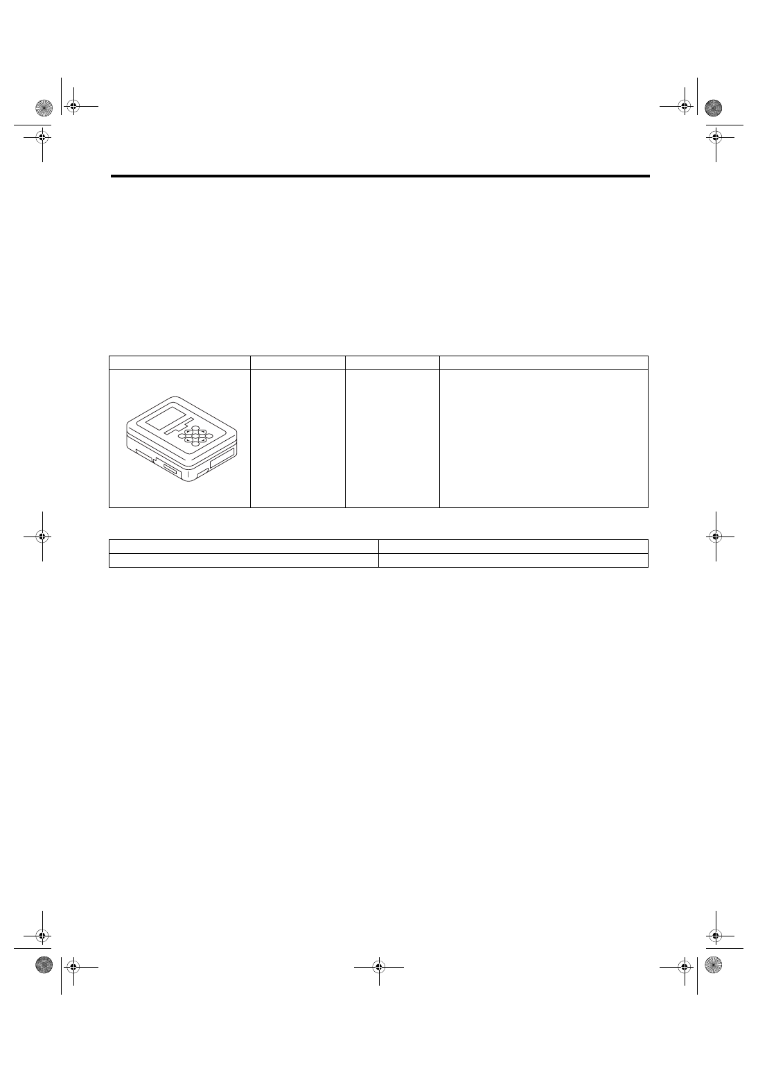
B: PREPARATION TOOL
1. SPECIAL TOOL
2. GENERAL TOOL
C: INSPECTION
Measure the battery voltage and specific gravity of electrolyte.
Standard voltage:
12 V or more
Specific gravity:
1.260 or more
ILLUSTRATION
TOOL NUMBER
DESCRIPTION
REMARKS
1B022XU0
SUBARU SELECT
MONITOR III KIT
Used for troubleshooting the electrical system.
TOOL NAME
REMARKS
Circuit tester
Used for measuring resistance, voltage and current.
ST1B022XU0
Нет комментариевНе стесняйтесь поделиться с нами вашим ценным мнением.
Текст