Subaru Impreza 3 / Impreza WRX / Impreza WRX STI. Service manual — part 285
EN(H4DOTC)(diag)-364
Diagnostic Procedure with Diagnostic Trouble Code (DTC)
ENGINE (DIAGNOSTICS)
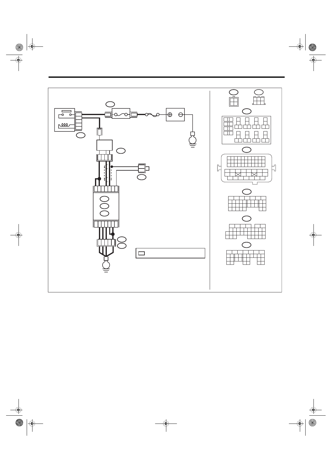
• Models with SI-DRIVE <Ref. to WI-48, WITH SI-DRIVE, WIRING DIAGRAM, Engine Electrical System.>
ECM
B138
6
4 5
3
2
1
1
2
3
4
B220
13
14
15 16
17
27
24
25
26
20
21
22
23
29
30
31
28
32 35
33
34
37
38
39
36
40
8
9
10
11 12
1
2
5
3
4
7
6
19
18
2
1
B220
15A
9
10
11
12
B220
D:
5
6
7
8
2
1
9
4
3
10
22 23
11 12 13 14 15
24 25
26
16 17
18 19 20 21
27
28 29
30 31
B137
C: B136
16
10 11 12 13 14 15
25
24
30
9
8
7
17 18 19 20
28
21 22 23
29
32
31
1
2
3
4
5
6
27
26
33 34 35
*
*
*
B138
D1
36
D3
A4
40
34
35
B21
E2
A6
A3
A:
54
52 53
50 51
48 49
46 47
45
44
42 43
40 41
38 39
36 37
34 35
33
32
31
30
29
28
27
26
25
24
23
22
21
20
11
10
9
19
18
17
16
8
7
6
5
15
14
13
12
4
3
2
1
D: B137
C: B136
A:
31
30
32
29
34
33
21
20
19
18
17
16
28
27
26
15
14
13
12
11
25
23
22
24
10
3
4
9
1
2
8
7
6
5
B134
B379
B21
B379
4
2
3
1
B134
C9
C19
C1
8
C6
C5
EN-08721
SBF-5
E
E
FRONT OXYGEN (A/F)
SENSOR
BATTERY
: TERMINAL No. OPTIONAL ARRANGEMENT
A/F, OXYGEN SENSOR
RELAY
FUSE
(RELAY BLOCK)
EN(H4DOTC)(diag)-365
Diagnostic Procedure with Diagnostic Trouble Code (DTC)
ENGINE (DIAGNOSTICS)
Step
Check
Yes
No
1
CHECK FOR ANY OTHER DTC ON DISPLAY. Is any other DTC displayed?
2
CHECK FRONT OXYGEN (A/F) SENSOR
CONNECTOR AND COUPLING CONNEC-
TOR.
Has water entered the connec-
tor?
Completely
remove any water
inside.
ECM
6
4 5
3
2
1
*
2
1
B220
15A
9
10
11
12
B220
*
*
1 2
3 4
D1
36
D3 A4
40
34
35
B21
E2
A6
A3
B220
13
14
15 16
17
27
24
25
26
20
21
22
23
29
30
31
28
32 35
33
34
37
38
39
36
40
8
9
10
11 12
1
2
5
3
4
7
6
19
18
B134
5
6
7
8
2
1
9
4
3
10
24
22 23
25
11 12 13 14 15
26 27
28
16 17
18 19 20 21
33 34
29
32
30 31
A:
D: B137
C: B136
B: B135
A:
T6
B134
C9
B30
C20
B6
*
*
B21
1 2 3 4
12 13 14 15
5 6 7 8
16 17 18 19
9 10 11
20 21 22
23 24 25 26 27 28 29 30 31 32 33
35
34
37
36
39
38
41
40
43
42
44 45
47
46
49
48
51
50
53
52
54
4
1
3
4
1
3
B19
T5
22
T5
B19
5
6
7
8
2
1
9
4
3
10
22 23
11 12 13 14 15
24 25
26
16 17
18 19 20 21
27
28 29
30 31
B135
B:
5
6
7
8
2
1
9
4
3
10
24
22 23
25
11 12 13 14 15
26 27
28
16 17 18 19
20 21
29 30 31
32 33
34 35
B136
C:
5
6
7 8
2
1
9
4
3
10
24
22 23
25
11 12 13 14 15
26 27
28
16
17 18 19 20 21
33 34
29
32
30
31
35
D: B137
B19
T6
B83
B138
B138
B83
EN-08723
SBF-5
E
E
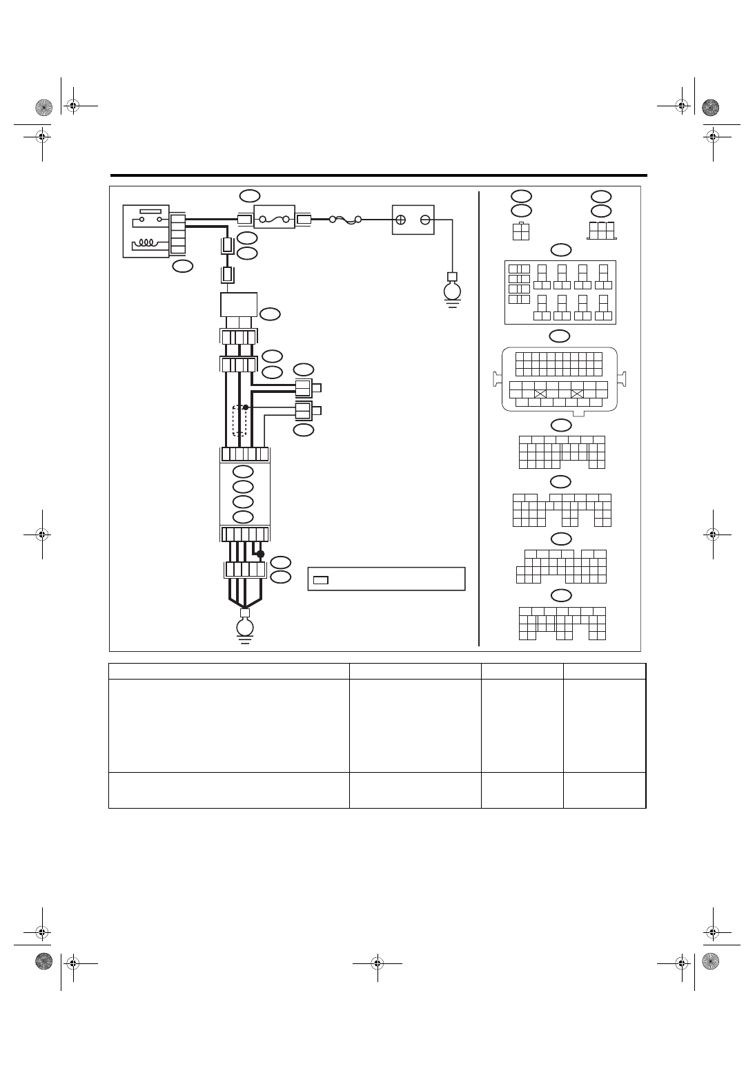
BATTERY
: TERMINAL No. OPTIONAL ARRANGEMENT
REAR
OXYGEN SENSOR
A/F, OXYGEN SENSOR
RELAY
FUSE
(RELAY BLOCK)
EN(H4DOTC)(diag)-366
Diagnostic Procedure with Diagnostic Trouble Code (DTC)
ENGINE (DIAGNOSTICS)
3
CHECK HARNESS BETWEEN ECM AND
FRONT OXYGEN (A/F) SENSOR CONNEC-
TOR.
1) Turn the ignition switch to OFF.
2) Disconnect the connectors from ECM and
front oxygen (A/F) sensor.
3) Measure the resistance of harness between
ECM connector and front oxygen (A/F) sensor
connector.
Connector & terminal
Models without SI-DRIVE
(B136) No. 19 — (E22) No. 1:
(B136) No. 18 — (E22) No. 3:
Models with SI-DRIVE
(B136) No. 19 — (B379) No. 4:
(B136) No. 18 — (B379) No. 3:
Is the resistance less than 1 Ω? Go to step
Repair the open
circuit of harness
between ECM con-
nector and front
oxygen (A/F) sen-
sor connector.
4
CHECK HARNESS BETWEEN ECM AND
FRONT OXYGEN (A/F) SENSOR CONNEC-
TOR.
Measure the resistance between ECM connec-
tor and chassis ground.
Connector & terminal
(B136) No. 19 — Chassis ground:
(B136) No. 18 — Chassis ground:
Is the resistance 1 MΩ or
more?
Repair the short
circuit to ground in
harness between
ECM connector
and front oxygen
(A/F) sensor con-
nector.
5
CHECK OUTPUT SIGNAL FOR ECM.
1) Connect the connector to ECM.
2) Turn the ignition switch to ON.
3) Measure the voltage between front oxygen
(A/F) sensor connector and chassis ground.
Connector & terminal
Models without SI-DRIVE
(E22) No. 1 (+) — Chassis ground (–):
Models with SI-DRIVE
(B379) No. 4 (+) — Chassis ground (–):
Is the voltage 4.5 V or more?
6
CHECK OUTPUT SIGNAL FOR ECM.
Measure the voltage between front oxygen (A/F)
sensor connector and chassis ground.
Connector & terminal
Models without SI-DRIVE
(E22) No. 3 (+) — Chassis ground (–):
Models with SI-DRIVE
(B379) No. 3 (+) — Chassis ground (–):
Is the voltage 4.95 V or more? Go to step
7
CHECK OUTPUT SIGNAL FOR ECM.
Measure the voltage between front oxygen (A/F)
sensor connector and chassis ground.
Connector & terminal
Models without SI-DRIVE
(E22) No. 3 (+) — Chassis ground (–):
(E22) No. 1 (+) — Chassis ground (–):
Models with SI-DRIVE
(B379) No. 3 (+) — Chassis ground (–):
(B379) No. 4 (+) — Chassis ground (–):
Is the voltage 8 V or more?
Repair the poor
contact of ECM
connector.
8
CHECK EXHAUST SYSTEM.
Are there holes or loose bolts
on exhaust system?
Repair the exhaust
system.
Step
Check
Yes
No
EN(H4DOTC)(diag)-367
Diagnostic Procedure with Diagnostic Trouble Code (DTC)
ENGINE (DIAGNOSTICS)
9
CHECK AIR INTAKE SYSTEM.
Are there holes, loose bolts or
disconnection of hose on air
intake system?
Repair the air
intake system.
10
CHECK FUEL PRESSURE.
WARNING:
Place “NO OPEN FLAMES” signs near the
working area.
CAUTION:
Be careful not to spill fuel.
1) Connect the front oxygen (A/F) sensor con-
nector.
2) Measure the fuel pressure while discon-
necting pressure regulator vacuum hose from
intake manifold. <Ref. to ME(STI)-25, INSPEC-
TION, Fuel Pressure.> <Ref. to ME(w/o STI)-
24, INSPECTION, Fuel Pressure.>
CAUTION:
Release fuel pressure before removing the
fuel pressure gauge.
NOTE:
If fuel pressure does not increase, squeeze the
fuel return hose 2 to 3 times, then measure fuel
pressure again.
Is the measured value 284 —
314 kPa (2.9 — 3.2 kgf/cm
2
, 41
— 46 psi)?
Check the fuel
pump and fuel
delivery line.
• Models without
SI-DRIVE <Ref. to
FU(w/o STI)-79,
INSPECTION,
Fuel Pump.> <Ref.
to FU(w/o STI)-93,
INSPECTION,
Fuel Delivery,
Return and Evapo-
ration Lines.>
• Models with SI-
DRIVE <Ref. to
FU(STI)-81,
INSPECTION,
Fuel Pump.> <Ref.
to FU(STI)-97,
INSPECTION,
Fuel Delivery,
Return and Evapo-
ration Lines.>
11
CHECK FUEL PRESSURE.
After connecting the pressure regulator vacuum
hose, measure fuel pressure. <Ref. to ME(STI)-
25, INSPECTION, Fuel Pressure.> <Ref. to
ME(w/o STI)-24, INSPECTION, Fuel Pres-
sure.>
CAUTION:
Release fuel pressure before removing the
fuel pressure gauge.
NOTE:
• If fuel pressure does not increase, squeeze
fuel return hose 2 to 3 times, then measure fuel
pressure again.
• If the measured value at this step is out of
specification, check or replace pressure regula-
tor and pressure regulator vacuum hose.
Is the measured value 230 —
260 kPa (2.4 — 2.7 kgf/cm
2
, 33
— 38 psi)?
Check the fuel
pump and fuel
delivery line.
• Models without
SI-DRIVE <Ref. to
FU(w/o STI)-79,
INSPECTION,
Fuel Pump.> <Ref.
to FU(w/o STI)-93,
INSPECTION,
Fuel Delivery,
Return and Evapo-
ration Lines.>
• Models with SI-
DRIVE <Ref. to
FU(STI)-81,
INSPECTION,
Fuel Pump.> <Ref.
to FU(STI)-97,
INSPECTION,
Fuel Delivery,
Return and Evapo-
ration Lines.>
Step
Check
Yes
No
Нет комментариевНе стесняйтесь поделиться с нами вашим ценным мнением.
Текст