Subaru Impreza 3 / Impreza WRX / Impreza WRX STI. Service manual — part 681
WW-5
General Description
WIPER AND WASHER SYSTEMS
D: PREPARATION TOOL
1. SPECIAL TOOL
2. GENERAL TOOL
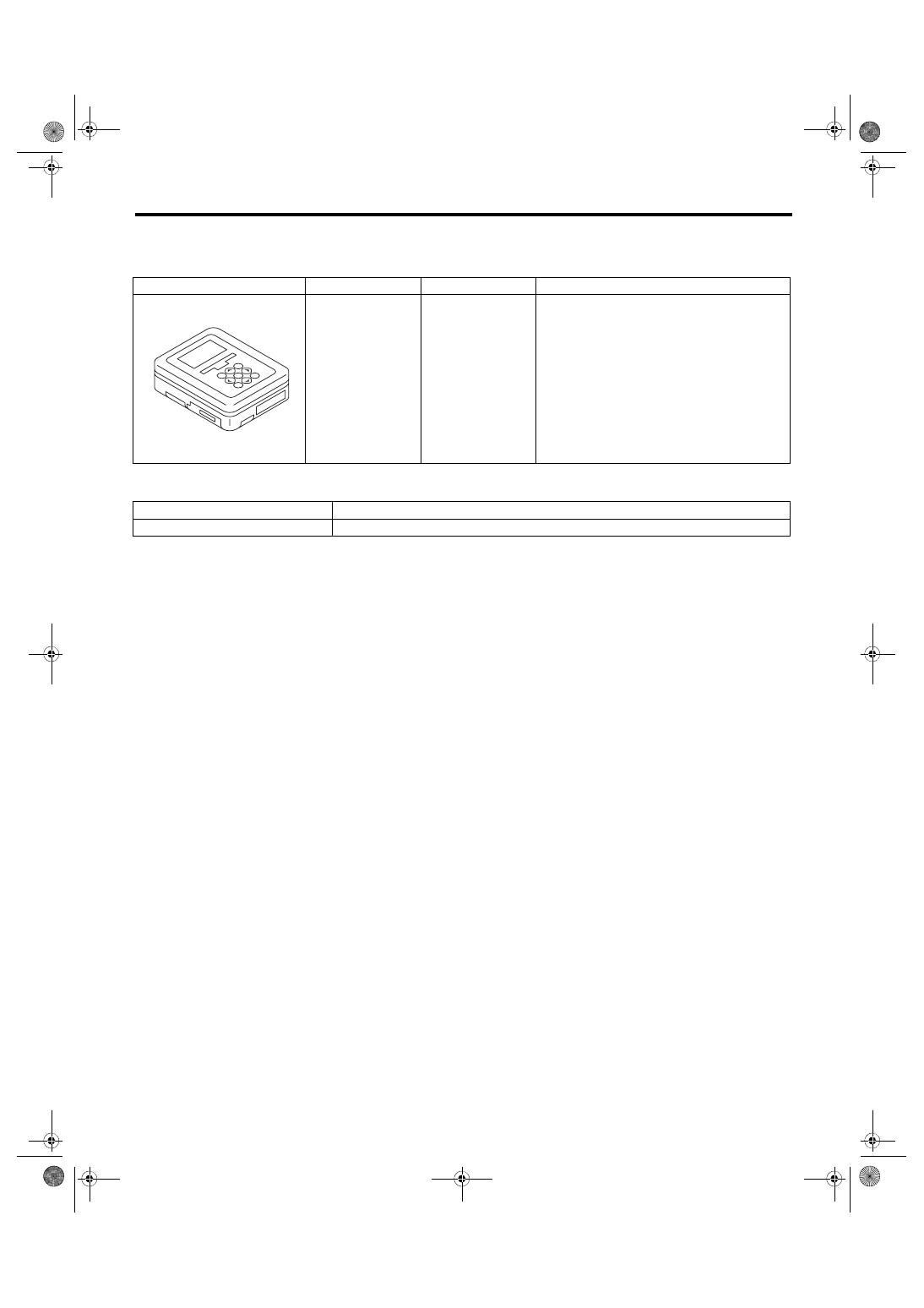
ILLUSTRATION
TOOL NUMBER
DESCRIPTION
REMARKS
1B022XU0
SUBARU SELECT
MONITOR III KIT
Used for setting of each function and trouble-
shooting for electrical system.
TOOL NAME
REMARKS
Circuit tester
Used for checking voltage and continuity.
ST1B022XU0
WW-6
Wiper and Washer System
WIPER AND WASHER SYSTEMS
2. Wiper and Washer System
A: WIRING DIAGRAM
1. WIPER AND WASHER (FRONT)
2. WIPER AND WASHER (REAR)
Refer to “Rear Wiper and Washer System” in the wiring diagram. <Ref. to WI-110, WIRING DIAGRAM, Rear
B: INSPECTION
C: NOTE
For procedure of each component of the wiper and washer system, refer to the respective sections.
• Combination switch (Wiper): <Ref. to WW-7, Combination Switch (Wiper).>
• Wiper blade: <Ref. to WW-11, Wiper Blade.>
• Front wiper arm: <Ref. to WW-16, Front Wiper Arm.>
• Front wiper motor and link: <Ref. to WW-17, Front Wiper Motor and Link.>
• Rear wiper arm: <Ref. to WW-20, Rear Wiper Arm.>
• Rear wiper motor: <Ref. to WW-21, Rear Wiper Motor.>
• Washer tank and motor: <Ref. to WW-14, Washer Tank and Motor.>
• Front washer nozzle: <Ref. to WW-19, Front Washer Nozzle.>
• Rear washer nozzle: <Ref. to WW-22, Rear Washer.>
Symptoms
Repair order
Wiper and washers do not operate.
1. Wiper fuse
2. Combination switch
3. Wiper motor assembly
4. Wiring harness
Wipers do not operate in LO or HI.
1. Combination switch
2. Wiper motor assembly
3. Wiring harness
Wipers do not operate in INT.
1. Combination switch
2. Wiper motor assembly
3. Wiring harness
Washer motor does not operate.
1. Washer switch
2. Washer motor
3. Wiring harness
Wipers do not operate when washer switch is ON.
1. Wiper motor assembly
2. Wiring harness
Washer fluid spray does not operate properly.
1. Washer motor
2. Washer hose and nozzle
WW-7
Combination Switch (Wiper)
WIPER AND WASHER SYSTEMS
3. Combination Switch (Wiper)
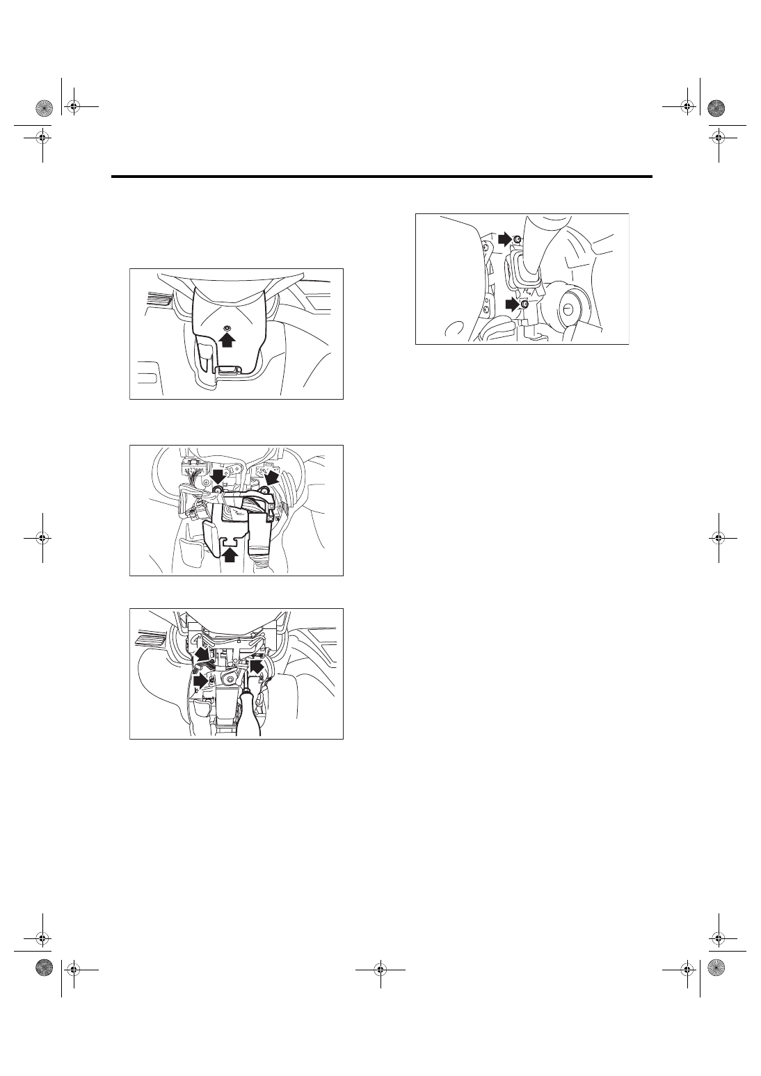
A: REMOVAL
1) Disconnect the ground cable from battery.
2) Remove the screws and remove the steering
column cover lower.
3) Remove the harness cover lock.
4) Remove the screws and detach the knee protec-
tor.
5) Remove the mounting screws of steering col-
umn cover upper.
6) Disconnect the connector from wiper switch.
7) Remove the screws and then remove the wiper
switch.
B: INSTALLATION
Install each part in the reverse order of removal.
WW-00547
LI-01143
LI-01144
WW-00300
WW-8
Combination Switch (Wiper)
WIPER AND WASHER SYSTEMS
C: INSPECTION
• Inspect the continuity between each connector
terminal.
Replace the switch if the inspection result is not
within the standard value.
1. FRONT WIPER
1) Check with Subaru Select Monitor
When the front wiper switch is operated, check the
input signal using the Subaru Select Monitor.
(1) Prepare the Subaru Select Monitor kit.
(2) Turn the ignition switch to ON.
(3) On «System Selection Menu» display, se-
lect {Integ. unit mode}.
(4) Display the {Current Data Display & Save},
and select {Fr wiper input}.
(5) Check the input signal when the front wiper
switch is set to LO or HI.
Does the input signal change between ON ←→
OFF correctly?
• Yes → Finish the diagnosis.
• No →
1. Check the harness.
2. Check the wiper motor.
3. Check ACC input voltage of body inte-
grated unit.
Connector & terminal
(B281) No. 5 (+) — Chassis ground (–):
4. Replace the body integrated unit. <Ref. to
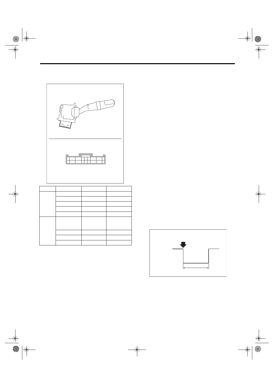
2) Check the intermittent operation (inspection of
the wiper switch alone)
(1) Set the voltage meter between terminal No.
7 (+) and No. 2 (–).
(2) Connect the battery to connector. (terminal
No. 17 (+), terminal No. 2 & 16 (–))
(3) Turn the front wiper switch to INT.
(4) Connect the battery (+) to the terminal No.
16 for 5 seconds.
(5) Connect the battery (–) to the terminal No.
16, and check the voltage between terminal No.
7 — No. 2 when performing the intermittent op-
eration.
(6) Perform step (1) to (5) above when intermit-
tent control switch is in MIN and MAX, and re-
place the switch if the operation is not as
specified.
Intermittent stationary time
MIN: Approx. 4 seconds
MAX: Approx. 19 seconds
Switch position
Terminal No.
Standard
Front
OFF
7 and 16
Less than 1 Ω
INT
7 and 16
Less than 1 Ω
LO
7 and 17
Less than 1 Ω
HI
8 and 17
Less than 1 Ω
Washer ON
2 and 11
Less than 1 Ω
Rear
OFF
2 and 10
10 and 12
2 and 12
1 MΩ or more
INT
2 and 13
Less than 1 Ω
ON
2 and 10
Less than 1 Ω
Washer ON
2 and 12
Less than 1 Ω
WW-00301
8
7 6 5 4 3
2 1
9
17
16 1514 13 12
11 10
18
(A): Connect the battery (–) to the terminal No. 16.
S: Intermittent downtime (sec.)
WW-00393
(A)
S
12 V
0 V
Нет комментариевНе стесняйтесь поделиться с нами вашим ценным мнением.
Текст