Subaru Impreza 3 / Impreza WRX / Impreza WRX STI. Service manual — part 720
SL-29
Security System
SECURITY AND LOCKS
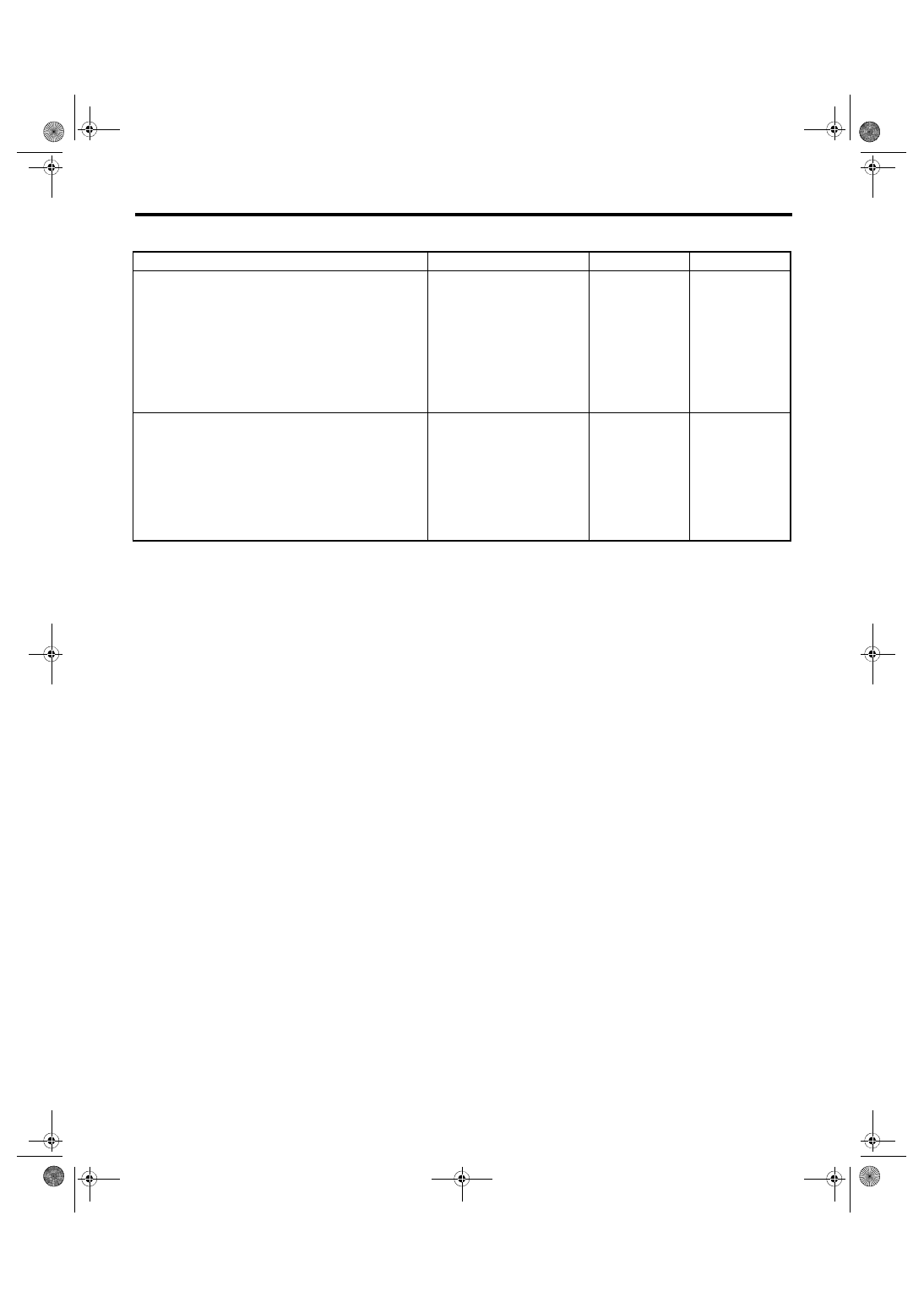
5. CHECK IGNITION SWITCH CIRCUIT
Step
Check
Yes
No
1
CHECK IGNITION SWITCH VOLTAGE.
1) Prepare the Subaru Select Monitor kit.
2) Turn the ignition switch to ON (engine OFF)
and run the “PC application for Subaru Select
Monitor”.
3) On «System Selection Menu» display,
select {Integ. unit mode}.
4) Select the {Current Data Display & Save}.
5) Select the {BATT voltage} and {IG power
supply voltage}.
Is the {IG power supply voltage}
within ±1 V against {BATT volt-
age}?
The ignition switch
input circuit is OK.
2
CHECK IGNITION SWITCH CIRCUIT.
1) Turn the ignition switch to OFF.
2) Disconnect the harness connector of body
integrated unit.
3) Turn the ignition switch to ON.
4) Measure the voltage between harness con-
nector terminal and chassis ground.
Connector & terminal
(B280) No. 1 (+) — Chassis ground (–):
Is the voltage 10 V or more?
Check body inte-
grated unit. <Ref.
to LAN(diag)-2,
Basic Diagnostic
Procedure.>
Check the harness
for open or short
circuit between
body integrated
unit and fuse.
SL-30
Front Inner Remote
SECURITY AND LOCKS
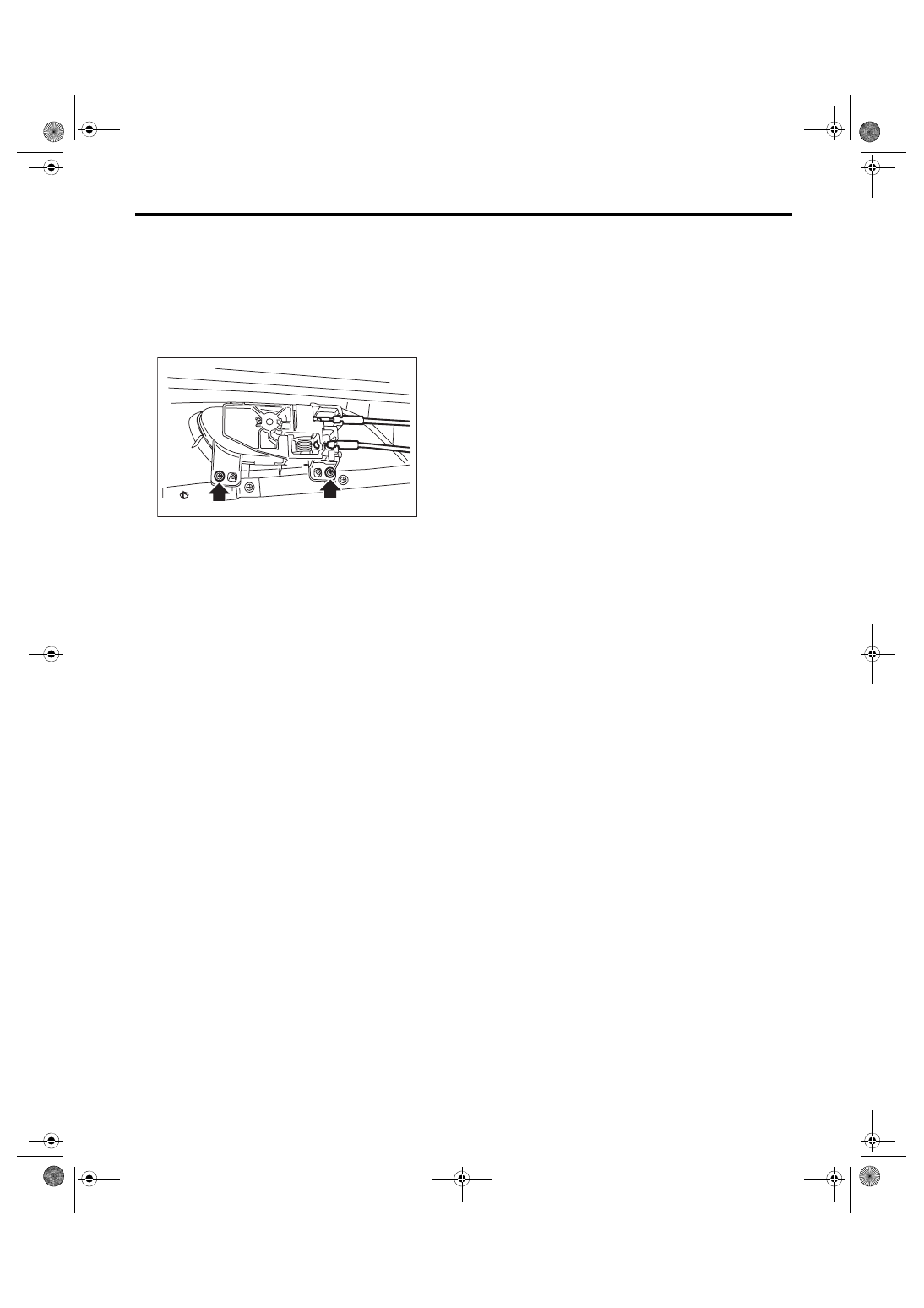
5. Front Inner Remote
A: REMOVAL
1) Remove the front door trim. <Ref. to EI-45, RE-
2) Remove the cable from the cable holder.
3) Remove the screws, and remove the inner re-
mote handle.
B: INSTALLATION
Install each part in the reverse order of removal.
C: INSPECTION
Check if the front remote handle operates normally.
• If the lever is faulty, replace the front inner re-
mote handle.
• If the cable is deformed, replace the front door
latch and door lock actuator assembly.
SL-00734
SL-31
Front Outer Handle
SECURITY AND LOCKS
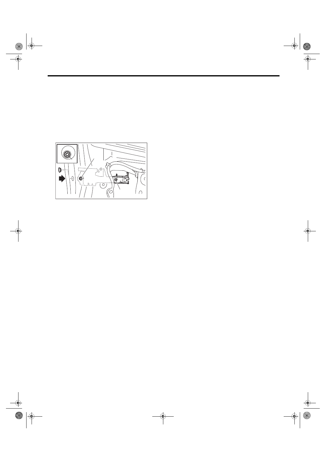
6. Front Outer Handle
A: REMOVAL
1) Raise the front door glass to the top position.
2) Remove the front door trim. <Ref. to EI-45, RE-
3) Remove the sealing cover. <Ref. to EB-21, RE-
4) Remove the rod clamp.
5) Remove the plug at the rear of the door panel,
and loosen the TORX
®
bolt (1).
6) Remove the door outer handle cover.
7) Move the front outer handle towards the rear,
and remove the front outer handle.
CAUTION:
Do not apply excessive force to remove the
handle from the door panel. The door panel
may become deformed.
8) Remove the outer side spacer.
9) Loosen TORX
®
bolt (2).
10) Remove the frame assembly from inside the
door panel.
B: INSTALLATION
Install each part in the reverse order of removal.
Tightening torque:
Refer to “COMPONENT” of “General Descrip-
tion”. <Ref. to SL-2, DOOR LOCK ASSEM-
BLY, COMPONENT, General Description.>
C: INSPECTION
Check if the front outer handle operates normally.
• If the lever is faulty, replace the front outer han-
dle.
• If the rod is deformed, replace the front door latch
and door lock actuator assembly.
SL-00735
(1)
(1)
(2)
SL-32
Front Door Latch and Door Lock Actuator Assembly
SECURITY AND LOCKS
7. Front Door Latch and Door
Lock Actuator Assembly
A: REMOVAL
1) Raise the front door glass to the top position.
2) Disconnect the ground cable from battery.
3) Remove the front door trim. <Ref. to EI-45, RE-
4) Remove the sealing cover. <Ref. to EB-21, RE-
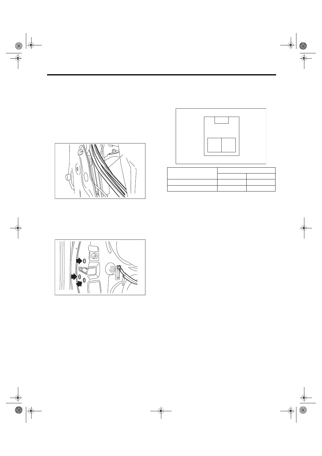
5) Remove the glass run rubber (A) partially.
6) Remove the bolts, and then remove the door
sash.
7) Remove the rod from the outer handle rod
clamp.
8) Disconnect the door lock actuator connector.
9) Remove the screws, and remove the front door
latch & door lock actuator assembly.
B: INSTALLATION
Install each part in the reverse order of removal.
Tightening torque:
Refer to “COMPONENT” of “General Descrip-
tion”. <Ref. to SL-2, DOOR LOCK ASSEM-
BLY, COMPONENT, General Description.>
C: INSPECTION
1. DOOR LATCH
Check if the front door latch operates normally.
• If the cable or rod is faulty, replace the front door
latch and door lock actuator assembly.
2. LOCK ACTUATOR
1) Disconnect the door lock actuator harness con-
nector.
2) Connect the battery to door lock actuator termi-
nals.
3) If the actuator does not operate normally, re-
place the front door latch and door lock actuator as-
sembly.
SL-00886
(A)
SL-00736
Actuator operation
Terminals
No. 1
No. 2
Lock → Unlock
–
+
Unlock → Lock
+
–
2 1
SL-00765
Нет комментариевНе стесняйтесь поделиться с нами вашим ценным мнением.
Текст