Subaru Impreza 3 / Impreza WRX / Impreza WRX STI. Service manual — part 54
EC(STI)-30
Secondary Air Combination Valve
EMISSION CONTROL (AUX. EMISSION CONTROL DEVICES)
B: INSTALLATION
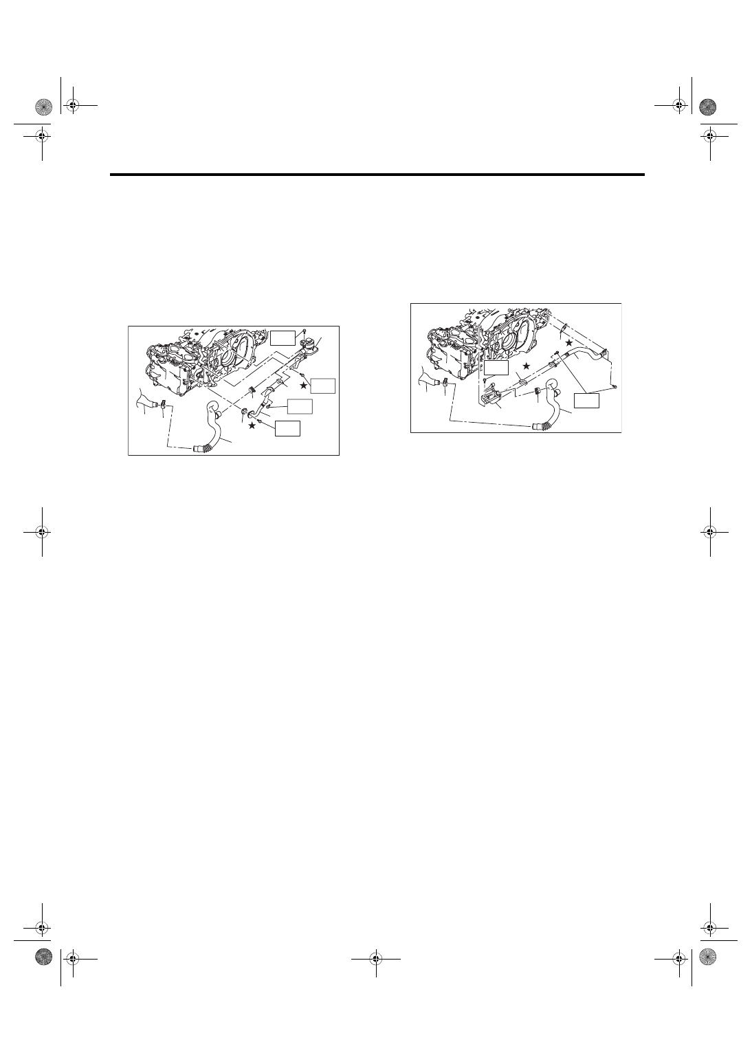
1. SECONDARY AIR COMBINATION
VALVE LH
Install in the reverse order of removal.
NOTE:
Use a new gasket.
Tightening torque:
T1: 9 N·m (0.9 kgf-m, 6.6 ft-lb)
T2: 19 N·m (1.9 kgf-m, 14.0 ft-lb)
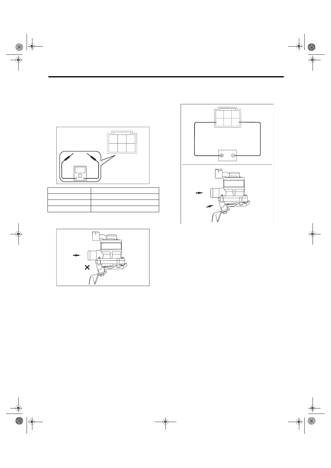
2. SECONDARY AIR COMBINATION
VALVE RH
Install in the reverse order of removal.
NOTE:
Use a new gasket.
Tightening torque:
T1: 9 N·m (0.9 kgf-m, 6.6 ft-lb)
T2: 19 N·m (1.9 kgf-m, 14.0 ft-lb)
(A) Secondary air combination valve LH
(B) Clip
(C) Air duct A
(D) Gasket
(E) Air duct B
(F) Secondary air pipe LH
(G) Gasket
(G)
(B)
(E)
(B)
(C)
(A)
(F)
(D)
EC-02722
T2
T1
T2
T2
(A) Secondary air combination valve RH
(B) Clip
(C) Air duct A
(D) Gasket
(E) Air duct B
(F) Secondary air pipe RH
(G) Gasket
(B)
(E)
(B)
(C)
(D)
(G)
(F)
(A)
EC-02723
T2
T1
EC(STI)-31
Secondary Air Combination Valve
EMISSION CONTROL (AUX. EMISSION CONTROL DEVICES)
C: INSPECTION
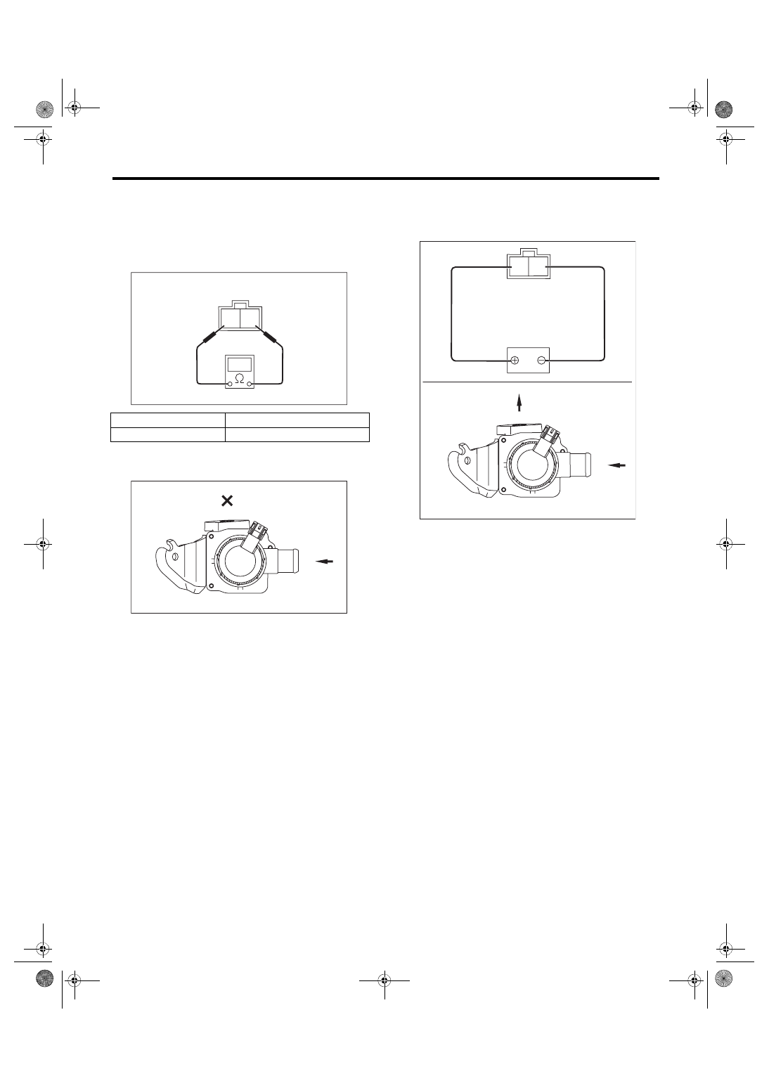
1. SECONDARY AIR COMBINATION
VALVE LH
1) Check that the secondary air combination valve
LH has no deformation, cracks or other damages.
2) Check the resistance between the terminals of
secondary air combination valve LH.
3) Check that air does not come out from (B) when
air is blown into (A).
4) Connect the battery positive terminal to the ter-
minal No. 6 and the battery negative terminal to the
terminal No. 4. Check that air is discharged from
(B), when supplying air to (A).
Terminal No.
Standard
4 and 6
5.0±0.5 Ω (when 20°C (68°F))
2 and 3
15 kΩ or less
1 and 2
4.5 kΩ or less
EC-02429
3
1
6 5 4
2
EC-02476
(A)
(B)
3
1
6 5 4
2
EC-02477
(A)
(B)
EC(STI)-32
Secondary Air Combination Valve
EMISSION CONTROL (AUX. EMISSION CONTROL DEVICES)
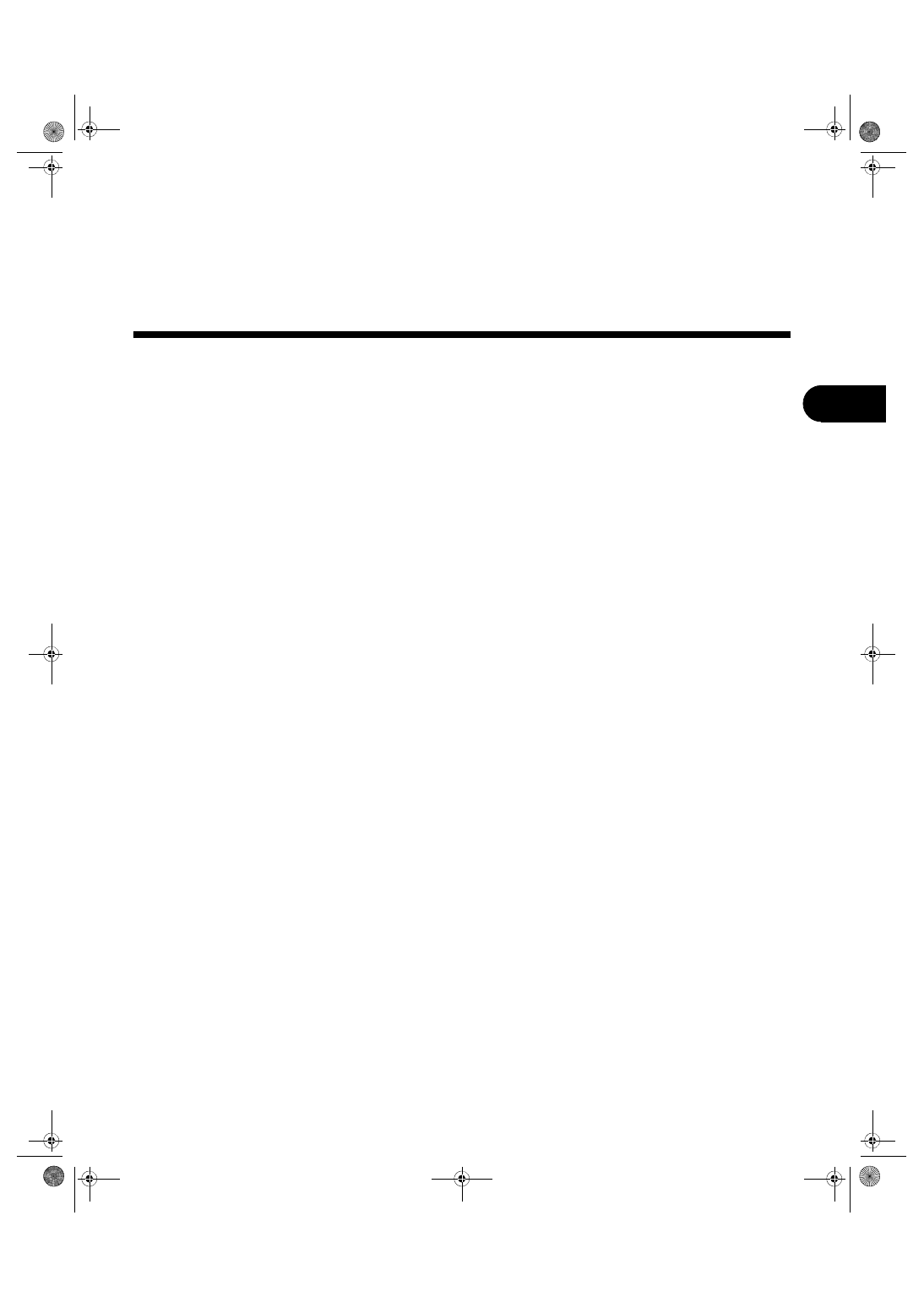
2. SECONDARY AIR COMBINATION
VALVE RH
1) Check that the secondary air combination valve
RH has no deformation, cracks or other damages.
2) Check the resistance between the terminals of
secondary air combination valve RH.
3) Check that air does not come out from (B) when
air is blown into (A).
4) Connect the battery positive terminal to the ter-
minal No. 2 and the battery negative terminal to the
terminal No. 1. Check that air is discharged from
(B), when supplying air to (A).
3. OTHER INSPECTIONS
1) Check that the secondary air pipe has no defor-
mation, cracks or other damages.
2) Check that the air duct has no cracks, damage
or loose part.
Terminal No.
Standard
1 and 2
5.0±0.5 Ω (when 20°C (68°F))
2 1
EC-02428
EC-02478
(A)
(B)
EC-02479
2 1
(A)
(B)
INTAKE (INDUCTION)
IN(STI)
Page
General Description . . . . . . . . . . . . . . . . . . . . ...2
Air Cleaner Element . . . . . . . . . . . . . . . . . . . . ...7
Air Cleaner Case . . . . . . . . . . . . . . . . . . . . . . 8
Air Intake Duct . . . . . . . . . . . . . . . . . . . . . . ..10
Intake Duct . . . . . . . . . . . . . . . . . . . . . . . ...11
Intercooler . . . . . . . . . . . . . . . . . . . . . . . . 12
Turbocharger . . . . . . . . . . . . . . . . . . . . . . . 15
Air By-pass Valve . . . . . . . . . . . . . . . . . . . . . .19
Resonator Chamber . . . . . . . . . . . . . . . . . . . . .20
Нет комментариевНе стесняйтесь поделиться с нами вашим ценным мнением.
Текст